Rendering synthetic objects into real scenes: bridging traditional and image-based graphics with global illumination and high dynamic range photography

P. Debevec

article1998SIGGRAPH1,378 citations

Introduces a technique that uses high dynamic range light probes and differential rendering to realistically insert synthetic 3D objects into real-world photographs with physically accurate lighting, shadows, and reflections.

Listen

Seamlessly inserting synthetic objects into real photographs or existing video has historically been a labor-intensive, error-prone task in computer graphics, visual effects, and architectural visualization. Conventional methods rely heavily on artists manually recreating physical light sources or hand-painting complex shadows, reflections, and color shifts. These manual approaches struggle to capture the full dynamic range of real environments and fail to accurately model the indirect interplay of light between virtual objects and real surfaces.

The article demonstrates a generalized framework that uses high dynamic range photography and global illumination to realistically render synthetic objects into real scenes. It introduces a practical workflow that illuminates virtual assets using measured real-world radiance and accounts for physical light exchanges—including soft shadows, caustics, and mutual reflections—without requiring complete 3D models or full material specifications of the entire environment.

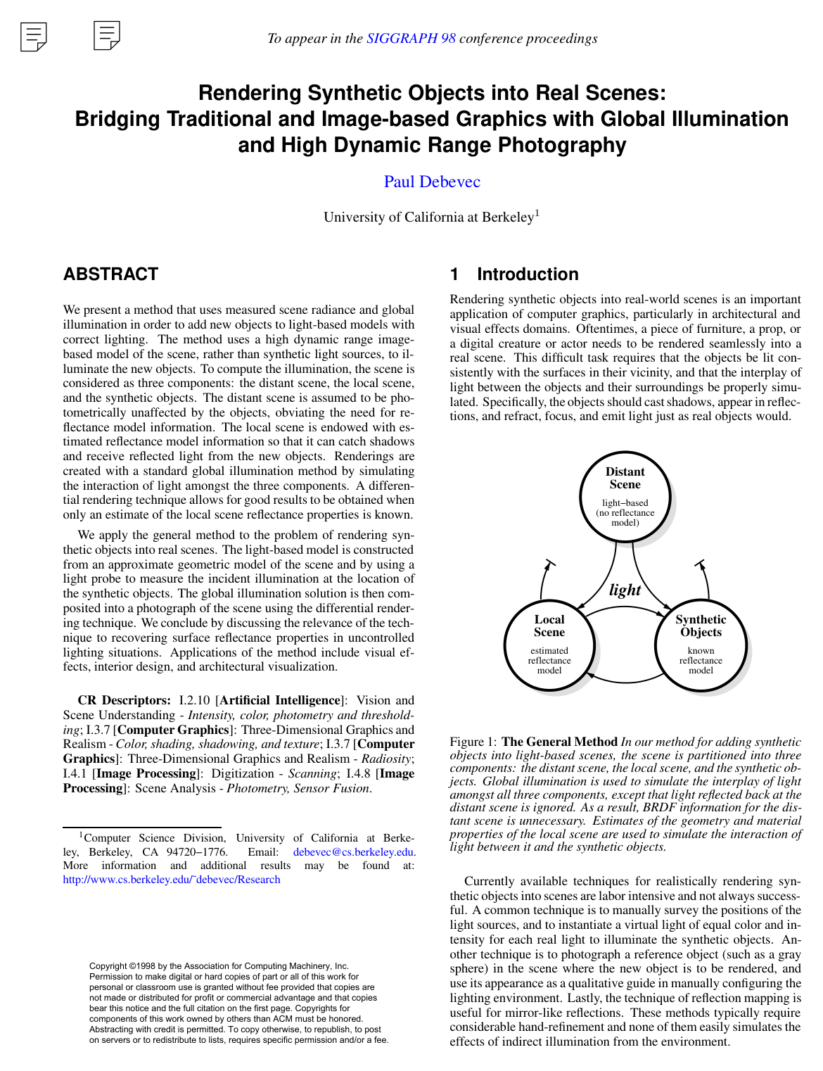
The approach operates by dividing a scene into three core components: the distant scene, the local scene, and the synthetic objects. The distant scene is represented as a light-based model constructed from omnidirectional radiance measurements captured with a light probe, such as a photographed mirrored sphere. This distant model emits real-world light toward the objects and local surfaces while ignoring negligible back-reflections. The local scene is given approximate geometry and estimated material reflectance properties to capture shadows and reflections. Global illumination algorithms simulate the lighting interaction across all components. To resolve inaccuracies in the local scene's estimated material properties, the approach introduces a differential rendering technique that subtracts a simulation of the unmodified local scene from the modified scene and composites the resulting lighting difference onto the original background plate.

The investigation produced four central findings. First, capturing the full high dynamic range of an environment is essential for realistic rendering; truncating bright light sources to low dynamic range values causes severe color imbalances, darkens rough or diffuse surfaces, and fails to form proper highlights. Second, partitioning the environment relieves the need to know the material reflectance of the distant scene, drastically reducing computational overhead and manual data acquisition. Third, the differential rendering method effectively conceals local surface modeling errors, eliminating visible borders and preserving the underlying surface texture, ambient reflections, and photographic detail. Fourth, a basic iterative comparison between measured irradiance and observed radiance allows for the approximate recovery of unknown diffuse reflectance properties in the local environment.

These findings provide significant operational advantages for digital production pipelines. By replacing manual lighting guesswork with physically measured radiance maps and differential updates, production teams can dramatically reduce manual labor costs, streamline rendering turnaround times, and improve visual consistency. The technique eliminates the high computational risk of simulating massive, fully modeled environments, delivering photorealistic compositing using standard global illumination software and commonly available camera equipment.

Organizations in architectural design and visual effects should adopt light probe image capture and high dynamic range panoramic lighting pipelines to automate scene illumination. Next steps should focus on extending the framework to optimize rendering efficiency, such as automatically detecting concentrated light sources to accelerate direct lighting calculations and integrating incremental algorithms to support moving objects. Users should note current limitations: extreme inaccuracies in local scene material estimates can degrade final composite quality, and mirrored reflections of the local scene may still reveal underlying geometry simplifications.

Debevec (1998).pdf
  • Paper: Recovering high dynamic range radiance maps from photographs, Paul E. Debevec et al. (1997). This paper establishes the foundational high dynamic range photography method used by the source to measure and assemble real-world omnidirectional radiance maps.
  • Paper: The rendering equation, James T. Kajiya (1986). It introduces the fundamental global illumination rendering equation required to simulate indirect lighting, mutual reflections, and soft shadows between synthetic objects and the local scene.
  • Paper: Compositing digital images, Thomas K. Porter et al. (1984). It formalizes digital image compositing operations and alpha channel blending upon which the source's differential rendering and compositing pipeline is built.
  • Paper: A reflectance model for computer graphics, Robert L. Cook et al. (1981). It provides the physically based microfacet reflectance models necessary for accurately rendering synthetic material properties and highlights under captured illumination.
  • Paper: Light field rendering, Marc Levoy et al. (1996). It introduces light field representations that underpin the source's methodology of using measured incident radiance to bridge image-based and traditional rendering.
  • Paper: The lumigraph, Steven J. Gortler et al. (1996). It details capturing and sampling real-world plenoptic light distributions, providing theoretical and practical foundations for image-based scene lighting.
  • Paper: Models of light reflection for computer synthesized pictures, J. Blinn (1977). It develops specular highlight and Fresnel reflection approximations essential for modeling realistic light interactions on synthetic surfaces.
  • Paper: QuickTime VR: an image-based approach to virtual environment navigation, Shenchang Eric Chen (1995). It demonstrates panoramic environment capture techniques that paved the way for omnidirectional light probe modeling.
Cover for Rendering synthetic objects into real scenes: bridging traditional and image-based graphics with global illumination and high dynamic range photography

Abstract

We present a method that uses measured scene radiance and global illumination in order to add new objects to light-based models with correct lighting. The method uses a high dynamic range image-based model of the scene, rather than synthetic light sources, to illuminate the new objects. To compute the illumination, the scene is considered as three components: the distant scene, the local scene, and the synthetic objects. The distant scene is assumed to be photometrically unaffected by the objects, obviating the need for reflectance model information. The local scene is endowed with estimated reflectance model information so that it can catch shadows and receive reflected light from the new objects. Renderings are created with a standard global illumination method by simulating the interaction of light amongst the three components. A differential rendering technique allows for good results to be obtained when only an estimate of the local scene reflectance properties is known.

We apply the general method to the problem of rendering synthetic objects into real scenes. The light-based model is constructed from an approximate geometric model of the scene and by using a light probe to measure the incident illumination at the location of the synthetic objects. The global illumination solution is then composited into a photograph of the scene using the differential rendering technique. We conclude by discussing the relevance of the technique to recovering surface reflectance properties in uncontrolled lighting situations. Applications of the method include visual effects, interior design, and architectural visualization.

Table of Contents

  • 1 Introduction
  • 1.1 Overview
  • 2 Background and Related Work
  • 3 Illuminating synthetic objects with real light
  • 4 The General Method
  • 1. A light-based model of the distant scene
  • 3. Complete material-based models of the objects
  • 5 Compositing using a light probe
  • 5.1 Mapping from the probe to the scene model
  • 5.2 Creating renderings
  • 6 Improving quality with differential rendering
  • 7 Estimating the local scene BRDF
  • 8 Compositing Results
  • 9 Future work
  • 10 Conclusion
  • Acknowledgments
  • References

Knowls

  1. Knowl 1 — Differential Rendering for Local Scene Compositing

    equation

    Differential rendering compensates for discrepancies between an estimated material model of a real scene and its actual physical appearance when compositing synthetic objects into an image.

    The final rendered radiance LSfinalLS_{\text{final}} for the local scene is defined additively as:

    LSfinal=LSb+(LSobj−LSnoobj)LS_{\text{final}} = LS_b + (LS_{\text{obj}} - LS_{\text{noobj}})

    where:

    • LSbLS_b is the measured background radiance from the desired viewpoint (the background plate photograph).
    • LSobjLS_{\text{obj}} is the radiance of the local scene computed via global illumination with the synthetic objects present, using estimated geometry and material properties.
    • LSnoobjLS_{\text{noobj}} is the radiance of the local scene computed via global illumination without the synthetic objects present, using the same estimated geometry and material properties.

    The difference Errls=LSnoobj−LSbErr_{\text{ls}} = LS_{\text{noobj}} - LS_b represents the modeling error in the local scene BRDF and geometry. Subtracting this error yields LSfinal=LSobj−ErrlsLS_{\text{final}} = LS_{\text{obj}} - Err_{\text{ls}}.

    When synthetic objects darken the local surface (LSobj<LSnoobjLS_{\text{obj}} < LS_{\text{noobj}}), light is subtracted from the background plate to form shadows. When synthetic objects brighten the surface (LSobj>LSnoobjLS_{\text{obj}} > LS_{\text{noobj}}), light is added to generate reflections and caustics. Where synthetic objects have no photometric effect (LSobj=LSnoobjLS_{\text{obj}} = LS_{\text{noobj}}), LSfinalLS_{\text{final}} reduces exactly to the background image LSbLS_b.

    Alternatively, a multiplicative formulation compensates for relative error:

    LSfinal=LSb(LSobjLSnoobj)LS_{\text{final}} = LS_b \left( \frac{LS_{\text{obj}}}{LS_{\text{noobj}}} \right)

  2. Knowl 2 — Three-Component Scene Partitioning Framework

    model/method

    To render synthetic objects into real environments using global illumination without requiring complete geometric and reflectance reconstruction of the entire space, a scene is partitioned into three components:

    1. Distant Scene: The portion of the environment that is photometrically unaffected by the addition of synthetic objects. It is represented as a light-based model storing calibrated high dynamic range (HDR) radiance values mapped onto approximate distant geometry (e.g., an enclosing dome or box). In global illumination, it acts strictly as an emitter (e.g., using a glow material) and ignores light reflected back toward it, eliminating the need for distant BRDF information.
    2. Local Scene: The surfaces in the scene that photometrically interact with the synthetic objects (receiving shadows, reflections, and indirect illumination). It is represented as an approximate geometric proxy endowed with estimated material BRDF parameters so it can fully participate in global illumination simulations.
    3. Synthetic Objects: Virtual objects with fully defined geometry and arbitrary material properties (such as diffuse, rough specular, dielectric, metallic, or emissive materials).

    A standard global illumination engine computes the mutual light transport between all three components, but light transported toward the distant scene is discarded.

  3. Knowl 3 — Iterative Recovery of Local Scene Diffuse Reflectance

    algorithm

    When geometry and incident illumination are known, the diffuse reflectance (albedo) of the local scene can be estimated from observed radiance.

    For a perfectly diffuse surface with albedo ρd\rho_d, the reflected radiance Lr1(θr,ϕr)L_{r1}(\theta_r, \phi_r) is:

    Lr1(θr,ϕr)=ρd∫02π∫0π/2Li(θi,ϕi)cos⁡θisin⁡θi dθi dϕiL_{r1}(\theta_r, \phi_r) = \rho_d \int_0^{2\pi} \int_0^{\pi/2} L_i(\theta_i, \phi_i) \cos\theta_i \sin\theta_i \, d\theta_i \, d\phi_i

    where Li(θi,ϕi)L_i(\theta_i, \phi_i) is the incident radiance from direction (θi,ϕi)(\theta_i, \phi_i). Setting ρd=1.0\rho_d = 1.0 yields the ideal diffuse reference radiance Lr2(θr,ϕr)L_{r2}(\theta_r, \phi_r) under the same lighting.

    Input: Measured background image LSbLS_b, local scene geometry, distant scene light-based model
    Output: Estimated diffuse albedo ρd′\rho_d' for each surface patch and color channel
    Initialize ρd←1.0\rho_d \leftarrow 1.0 for all local scene patches across R, G, B channels
    repeat
        Render local scene without synthetic objects using global illumination to compute Lr2L_{r2}
        for each local scene surface patch do
            for each color channel c∈{R,G,B}c \in \{R, G, B\} do
                Compute updated albedo ρd′(c)←Lr1(c)Lr2(c)\rho_d'(c) \leftarrow \frac{L_{r1}(c)}{L_{r2}(c)} where Lr1(c)L_{r1}(c) is the observed radiance from LSbLS_b
            end for
        end for
        Update local scene BRDF parameters with ρd′\rho_d'
    until convergence or until maximum iterations reached
    return ρd′\rho_d'

    If there is no interreflection among local scene surfaces, a single iteration yields the exact albedo matching the observed radiance.

  4. Knowl 4 — Light-Based Scene Model

    definition

    A light-based model is a digital representation of a scene that stores absolute measures of radiance P(θ,ϕ,Vx,Vy,Vz)P(\theta, \phi, V_x, V_y, V_z) across 5D plenoptic space (or 7D when including time and wavelength/spectral channels), rather than material surface reflectance (BRDF) properties.

    It is distinguished from:

    • A material-based model, which consists of geometric surfaces, light source definitions, and BRDF parameters, and requires computing an illumination simulation to determine radiance.
    • An image-based model, which contains pixel values that have been distorted, clipped, or non-linearly mapped by camera sensor and display transfer functions rather than true physical radiance.
  5. Knowl 5 — Omnidirectional HDR Illumination Acquisition via Mirrored Sphere Probe

    model/method

    To acquire the incident illumination required to light synthetic objects, a spherical first-surface mirror (a polished steel ball) is placed at the target insertion location and photographed across a sequence of exposures (e.g., from 1/4 s1/4\text{ s} to 1/10000 s1/10000\text{ s} in one-stop increments).

    The multi-exposure sequence is fused into an omnidirectional high dynamic range (HDR) radiance map by inverting the camera response function. Rays traced from the camera center reflecting off the spherical surface sample incoming radiance across nearly the entire sphere of directions.

    The resulting radiance map is mapped onto an approximate proxy model of the distant scene (such as a ground plane and an enclosing finite bounding box or dome) positioned relative to the probe. This maps the directional and spatial distribution of both direct light sources and indirect environmental illumination into the global illumination simulator.

  6. Knowl 6 — Dual-Probe Artifact and Occlusion Removal

    model/method

    A single mirrored sphere light probe introduces systematic artifacts into the acquired environment map: the camera and photographer appear in the reflection, the sphere's support structure occludes the scene, the area directly behind the ball is occluded, and directions near the silhouette edge suffer from poor radial sampling resolution.

    To construct an artifact-free omnidirectional environment map, two light probe image sequences are captured from viewpoints oriented 90∘90^\circ apart relative to the center of the sphere. Combining and selectively compositing the two reconstructed HDR maps removes the camera and support apparatus and resolves sampling degradation near the silhouette boundaries.

  7. Knowl 7 — Differential Rendering Compositing Pipeline

    algorithm

    The complete procedure for inserting synthetic objects into a real photograph using light probe data and differential rendering proceeds as follows:

    Input: Background photograph LSbLS_b, light probe HDR radiance map, camera pose, 3D synthetic object models
    Output: Final composited image IfinalI_{\text{final}}
    Construct distant scene proxy geometry mapped with the HDR light probe radiance
    Construct local scene geometric proxy for surfaces near the insertion site
    Estimate local scene BRDF parameters
    Align virtual camera pose with the background photograph viewpoint
    Render LSobjLS_{\text{obj}}: Global illumination of distant scene, local scene proxy, and synthetic objects
    Render LSnoobjLS_{\text{noobj}}: Global illumination of distant scene and local scene proxy (without synthetic objects)
    Render binary mask MM: White for synthetic object pixels, black elsewhere (accounting for local/distant scene occluders)
    Compute difference image ΔLS←LSobj−LSnoobj\Delta LS \leftarrow LS_{\text{obj}} - LS_{\text{noobj}}
    for each pixel pp do
        if M(p)=1M(p) = 1 then
            Ifinal(p)←LSobj(p)I_{\text{final}}(p) \leftarrow LS_{\text{obj}}(p)
        else if pixel pp is on the local scene proxy then
            Ifinal(p)←LSb(p)+ΔLS(p)I_{\text{final}}(p) \leftarrow LS_b(p) + \Delta LS(p)
        else
            Ifinal(p)←LSb(p)I_{\text{final}}(p) \leftarrow LS_b(p)
        end if
    end for
    return IfinalI_{\text{final}}
  8. Knowl 8 — Failure of Low Dynamic Range Lighting for Environmental Illumination

    empirical result

    Using conventional low dynamic range (LDR) photographs as environment lighting maps severely degrades global illumination accuracy compared to high dynamic range (HDR) radiance maps where light source radiances are unclipped:

    1. Diffuse and Rough Materials: In LDR maps where peak intensities are clamped to ~2% of their physical values, surfaces with rough specular or diffuse reflectance appear drastically under-illuminated (up to a factor of 6 to 8 times too dark) because incoming light energy over the source solid angle is underrepresented.
    2. Shadow Contrast and Distinctness: HDR maps accurately generate distinct multiple soft and hard shadows with differing chromaticities corresponding to real light sources (e.g., sharp tungsten ceiling light shadows vs. soft blue-sky window shadows). LDR maps fail to generate noticeable directional shadows.
    3. Color Temperature Fidelity: Direct light sources (which may be 2 to 6 orders of magnitude brighter than ambient surfaces) have their true spectral balance preserved only in HDR, preventing severe color balance shifts on illuminated synthetic objects.
  9. Knowl 9 — Criteria for Partitioning Local vs. Distant Scene Elements

    assumption

    The assumption that distant scene elements can be modeled purely as emitters without BRDF properties holds only when synthetic objects do not perceptibly modify the appearance of those elements. A scene element must be assigned to the local scene (and given an approximate BRDF model) under any of four specific conditions:

    1. Collinear Concentrated Shadows: Concentrated light sources cause synthetic objects to cast visible shadows on distant surfaces lying collinear with the object and the source.
    2. Specular Caustics / Focused Light: Flat or curved specular synthetic objects focus significant reflected or refracted light onto distant surfaces.
    3. Specular Reflectors in the Environment: Distant surfaces with specular or mirror-like BRDFs reflect the synthetic object directly.
    4. Emissive Synthetic Objects: The synthetic object actively emits light (such as a virtual laser or lamp) that alters distant surface radiance.
  10. Knowl 10 — Secondary Reflection Limitation in Differential Rendering

    limitation

    Differential rendering corrects the appearance of the local scene only for rays traveling directly from the local scene to the camera viewpoint.

    When a shiny or reflective synthetic object reflects the adjacent local scene, the reflection displays the synthetic global illumination solution of the modeled proxy geometry with its estimated BRDF (LSobjLS_{\text{obj}}), rather than reflecting the real background surface details (such as table wood grain or unmodeled background reflections). Consequently, modeled local scene inaccuracies remain visible inside mirror reflections on synthetic objects.

Coverage note — None was omitted; all key theoretical principles, mathematical formulations, acquisition strategies, iterative BRDF estimation routines, empirical findings, and operational limitations are covered.

References

  1. 1.ADELSON, E. H., AND BERGEN, J. R. Computational Models of Visual Processing. MIT Press, Cambridge, Mass., 1991, ch. 1. The Plenoptic Function and the Elements of Early Vision.
  2. 2.AZARMI, M. Optical Effects Cinematography: Its Development, Methods, and Techniques. University Microfilms International, Ann Arbor, Michigan, 1973.
  3. 3.BLINN, J. F. Texture and reflection in computer generated images. Communications of the ACM 19, 10 (October 1976), 542–547.
  4. 4.CHEN, E. QuickTime VR - an image-based approach to virtual environment navigation. In SIGGRAPH ’95 (1995).
  5. 5.CHEN, S. E. Incremental radiosity: An extension of progressive radiosity to an interactive synthesis system. In SIGGRAPH ’90 (1990), pp. 135–144.
  6. 6.COHEN, M. F., CHEN, S. E., WALLACE, J. R., AND GREENBERG, D. P. A progressive refinement approach to fast radiosity image generation. In SIGGRAPH ’88 (1988), pp. 75–84.
  7. 7.CURLESS, B., AND LEVOY, M. A volumetric method for building complex models from range images. In SIGGRAPH ’96 (1996), pp. 303–312.
  8. 8.DANA, K. J., GINNEKEN, B., NAYAR, S. K., AND KOENDERINK, J. J. Reflectance and texture of real-world surfaces. In Proc. IEEE Conf. on Comp. Vision and Patt. Recog. (1997), pp. 151–157.
  9. 9.DEBEVEC, P. E., AND MALIK, J. Recovering high dynamic range radiance maps from photographs. In SIGGRAPH ’97 (August 1997), pp. 369–378.
  10. 10.DEBEVEC, P. E., TAYLOR, C. J., AND MALIK, J. Modeling and rendering architecture from photographs: A hybrid geometry- and image-based approach. In SIGGRAPH ’96 (August 1996), pp. 11–20.
  11. 11.DEBEVEC, P. E., YU, Y., AND BORSHUKOV, G. D. Efficient view-dependent image-based rendering with projective texture-mapping. Tech. Rep. UCB//CSD-98-1003, University of California at Berkeley, 1998.
  12. 12.DRETTAKIS, G., ROBERT, L., AND BOUGNOUX, S. Interactive common illumination for computer augmented reality. In 8th Eurographics workshop on Rendering, St. Etienne, France (May 1997), J. Dorsey and P. Slusallek, Eds., pp. 45–57.
  13. 13.FIELDING, R. The Technique of Special Effects Cinematography. Hastings House, New York, 1968.
  14. 14.FOURNIER, A., GUNAWAN, A., AND ROMANZIN, C. Common illumination between real and computer generated scenes. In Graphics Interface (May 1993), pp. 254–262.
  15. 15.GERSHBEIN, R., SCHRODER, P., AND HANRAHAN, P. Textures and radiosity: Controlling emission and reflection with texture maps. In SIGGRAPH ’94 (1994).
  16. 16.GORAL, C. M., TORRANCE, K. E., GREENBERG, D. P., AND BATTAILE, B. Modeling the interaction of light between diffuse surfaces. In SIGGRAPH ’84 (1984), pp. 213–222.
  17. 17.GORTLER, S. J., GRZESZCZUK, R., SZELISKI, R., AND COHEN, M. F. The Lumigraph. In SIGGRAPH ’96 (1996), pp. 43–54.
  18. 18.HECKBERT, P. S. Survey of texture mapping. IEEE Computer Graphics and Applications 6, 11 (November 1986), 56–67.
  19. 19.KAJIYA, J. The rendering equation. In SIGGRAPH ’86 (1986), pp. 143–150.
  20. 20.KARNER, K. F., MAYER, H., AND GERVAUTZ, M. An image based measurement system for anisotropic reflection. In EUROGRAPHICS Annual Conference Proceedings (1996).
  21. 21.KOENDERINK, J. J., AND VAN DOORN, A. J. Illuminance texture due to surface mesostructure. J. Opt. Soc. Am. 13, 3 (1996).
  22. 22.LAVEAU, S., AND FAUGERAS, O. 3-D scene representation as a collection of images. In Proceedings of 12th International Conference on Pattern Recognition (1994), vol. 1, pp. 689–691.
  23. 23.LEVOY, M., AND HANRAHAN, P. Light field rendering. In SIGGRAPH ’96 (1996), pp. 31–42.
  24. 24.MCMILLAN, L., AND BISHOP, G. Plenoptic Modeling: An image-based rendering system. In SIGGRAPH ’95 (1995).
  25. 25.NAKAMAE, E., HARADA, K., AND ISHIZAKI, T. A montage method: The overlaying of the computer generated images onto a background photograph. In SIGGRAPH ’86 (1986), pp. 207–214.
  26. 26.PORTER, T., AND DUFF, T. Compositing digital images. In SIGGRAPH 84 (July 1984), pp. 253–259.
  27. 27.SATO, Y., WHEELER, M. D., AND IKEUCHI, K. Object shape and reflectance modeling from observation. In SIGGRAPH ’97 (1997), pp. 379–387.
  28. 28.SMITH, T. G. Industrial Light and Magic: The Art of Special Effects. Ballantine Books, New York, 1986.
  29. 29.SZELISKI, R. Image mosaicing for tele-reality applications. In IEEE Computer Graphics and Applications (1996).
  30. 30.TURK, G., AND LEVOY, M. Zippered polygon meshes from range images. In SIGGRAPH ’94 (1994), pp. 311–318.
  31. 31.VEACH, E., AND GUIBAS, L. J. Metropolis light transport. In SIGGRAPH ’97 (August 1997), pp. 65–76.
  32. 32.WARD, G. J. Measuring and modeling anisotropic reflection. In SIGGRAPH ’92 (July 1992), pp. 265–272.
  33. 33.WARD, G. J. The radiance lighting simulation and rendering system. In SIGGRAPH ’94 (July 1994), pp. 459–472.
  34. 34.WATANABE, M., AND NAYAR, S. K. Telecentric optics for computational vision. In Proceedings of Image Understanding Workshop (IUW 96) (February 1996).
  35. 35.Y.CHEN, AND MEDIONI, G. Object modeling from multiple range images. Image and Vision Computing 10, 3 (April 1992), 145–155.

Citation

MLA
Debevec, P. “Rendering Synthetic Objects into Real Scenes”. Proceedings of the 25th Annual Conference on Computer Graphics and Interactive Techniques - SIGGRAPH '98, 1998, pp. 189–98, https://doi.org/10.1145/280814.280864.
APA
Debevec, P. (1998). Rendering synthetic objects into real scenes. Proceedings of the 25th Annual Conference on Computer Graphics and Interactive Techniques - SIGGRAPH '98, 189–198. https://doi.org/10.1145/280814.280864
Chicago
Debevec, P. 1998. “Rendering Synthetic Objects into Real Scenes”. Proceedings of the 25th Annual Conference on Computer Graphics and Interactive Techniques - SIGGRAPH '98, 189–98. https://doi.org/10.1145/280814.280864.
Harvard
Debevec, P. (1998) “Rendering synthetic objects into real scenes”, Proceedings of the 25th annual conference on Computer graphics and interactive techniques - SIGGRAPH '98. ACM Press, pp. 189–198. Available at: https://doi.org/10.1145/280814.280864.
Vancouver
1. Debevec P (1998) Rendering synthetic objects into real scenes. In: Proceedings of the 25th annual conference on Computer graphics and interactive techniques - SIGGRAPH '98. ACM Press, pp 189–198

BibTeX

@inproceedings{Debevec_1998, series={SIGGRAPH ’98}, title={Rendering synthetic objects into real scenes: bridging traditional and image-based graphics with global illumination and high dynamic range photography}, url={http://dx.doi.org/10.1145/280814.280864}, DOI={10.1145/280814.280864}, booktitle={Proceedings of the 25th annual conference on Computer graphics and interactive techniques  - SIGGRAPH ’98}, publisher={ACM Press}, author={Debevec, Paul}, year={1998}, pages={189–198}, collection={SIGGRAPH ’98} }
Metadata:Crossref

Access the Paper

This paper is available from its original source. Click below to access the PDF.

Open PDF