A reflectance model for computer graphics

Robert L. CookKenneth E. Torrance

article1981SIGGRAPH2,303 citations

Proposes a physics-based microfacet reflectance model that combines Fresnel reflection and geometrical attenuation to accurately simulate realistic surface appearance and wavelength-dependent color shifts across metals and nonmetals.

Listen

Synthesizing realistic computer-generated imagery requires accurate models of how physical materials interact with light. Prior illumination techniques in computer graphics typically assumed that highlights take on the color of the light source, which caused rendered objectsespecially metalsto exhibit an unnatural, uniform plastic appearance. The article set out to develop and demonstrate a comprehensive light-reflection model based on geometrical optics that accurately predicts the directional distribution, brightness, and color shifts of light reflected from both metallic and nonmetallic surfaces.

To achieve this, the article formulated a bidirectional reflectance framework incorporating microfacet surface slope distributions, shadowing and masking effects, and standard Fresnel optical equations. The methodology utilized measured physical reflectance spectra for real materials and standardized light source distributions. It mapped the resulting spectral energy distributions into monitor-specific display signals using standard colorimetry principles and gamut-mapping techniques.

The findings show that specular highlight color is primarily determined by the material's properties rather than solely by the light source, which directly explains and resolves the artificial plastic sheen of earlier rendering models. The model demonstrates that metals reflect light almost entirely at the surface without a significant diffuse component, while non-homogeneous materials like plastics produce colored diffuse scattering beneath the surface beneath a neutral specular highlight. Furthermore, the analysis reveals a significant color shift toward the light source's color at extreme grazing angles, which can be efficiently approximated without full spectral recalculation. Finally, the research showed that complex surface finishes can be realistically represented by combining multiple facet slope roughness distributions.

These results establish that physically based reflectance and accurate color reproduction are essential for high-fidelity image rendering across diverse materials and lighting conditions. While full spectral and Fresnel evaluations increase computational workload, the article shows that practical approximations and precalculated lookup tables make the method computationally viable for production graphics. Adopting systems should implement these bidirectional reflectance equations alongside standard color-space transformations to achieve photorealistic visualization.

The framework operates under the assumptions of geometrical optics and neglects wavelength-dependent diffraction on near-mirror surfaces, inter-object reflections, and the environmental aging of materials such as oxidation layers. Despite these boundary constraints, the underlying physical principles provide high confidence in reliably distinguishing real-world materials in synthetic graphics.

Cover for A reflectance model for computer graphics

Abstract

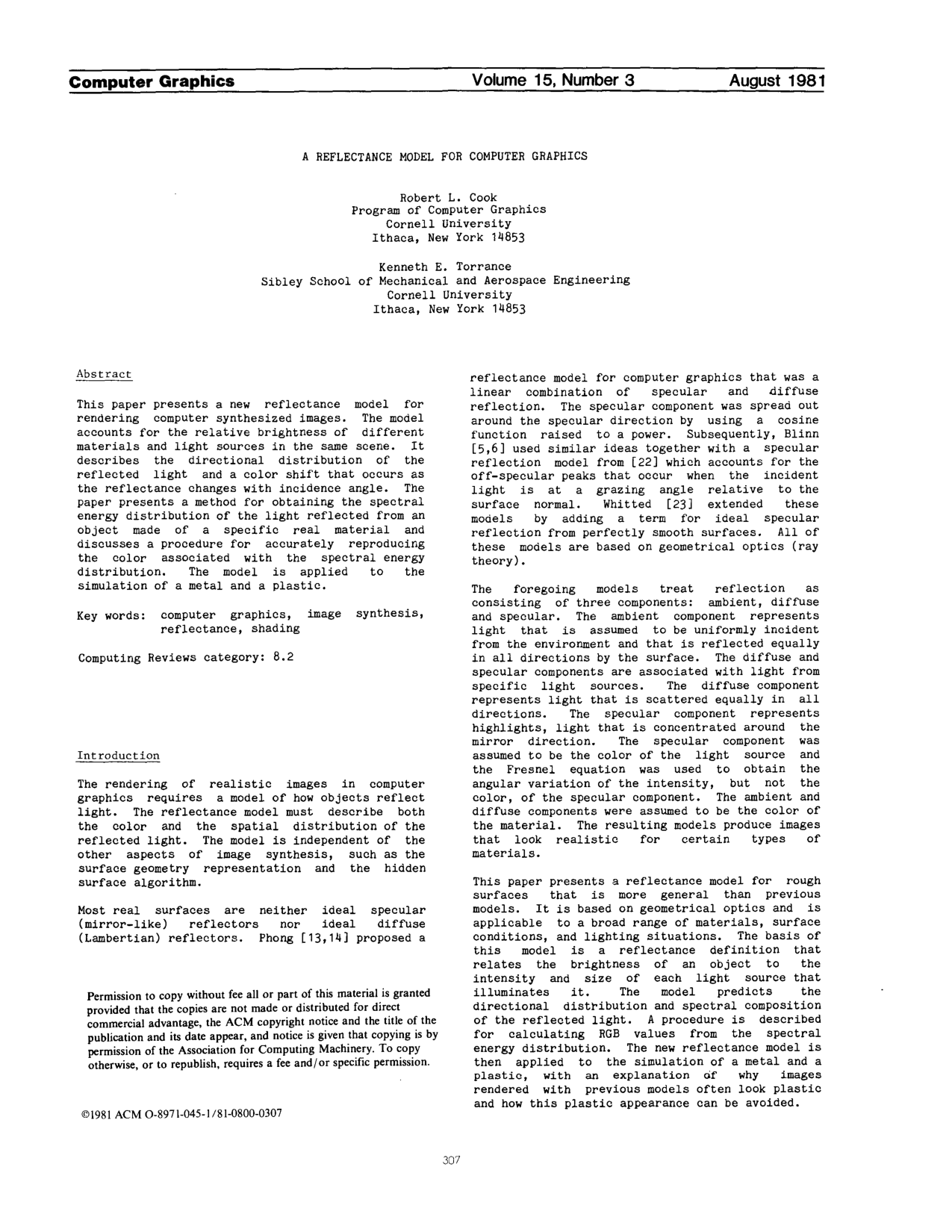
This paper presents a new reflectance model for rendering computer synthesized images. The model accounts for the relative brightness of different materials and light sources in the same scene. It describes the directional distribution of the reflected light and a color shift that occurs as the reflectance changes with incidence angle. The paper presents a method for obtaining the spectral energy distribution of the light reflected from an object made of a specific real material and discusses a procedure for accurately reproducing the color associated with the spectral energy distribution. The model is applied to the simulation of a metal and a plastic.

Table of Contents

  • Introduction
  • The Reflectance Model
  • Directional Distribution of the Reflected Lisht
  • Spectral Composition of the Reflected Light
  • Determining the RGB Values
  • Applications
  • Conclusions
  • Acknowl¢~$ement§
  • References

Knowls

  1. Knowl 1 — Cook-Torrance Reflectance Model Formulation

    model/method

    The Cook-Torrance reflectance model determines the total reflected light intensity IrI_r reaching an observer from ambient illumination and a collection of discrete light sources:

    Ir=IiaRa+lIil(NLl)dωil(sRs+dRd)I_r = I_{ia} R_a + \sum_l I_{il} (N \cdot L_l) \, d\omega_{il} (s R_s + d R_d)

    where:

    • IiaI_{ia} is the average intensity of the uniformly incident ambient light.
    • RaR_a is the ambient (hemispherical-directional) reflectance of the surface, which is a linear combination of RsR_s and RdR_d.
    • ll indexes each illuminating light source.
    • IilI_{il} is the average intensity of the incident light from light source ll.
    • NN is the unit surface normal vector.
    • LlL_l is the unit vector pointing toward light source ll.
    • dωild\omega_{il} is the solid angle subtended by light source ll.
    • ss is the fraction of total reflection that is specular (0s10 \le s \le 1).
    • dd is the fraction of total reflection that is diffuse (0d10 \le d \le 1), constrained such that s+d=1s + d = 1.
    • RsR_s is the bidirectional specular reflectance.
    • RdR_d is the bidirectional diffuse reflectance (assumed Lambertian, reflecting equally into all directions).

    When ambient light is partially blocked by nearby surfaces, the ambient reflected intensity is scaled as Ira=RaIiafI_{ra} = R_a I_{ia} f, where f=1π(NL)dωif = \frac{1}{\pi} \int (N \cdot L) \, d\omega_i is the unblocked fraction of the illuminating hemisphere (f=1f = 1 for an unobstructed hemisphere).

  2. Knowl 2 — Microfacet Specular Reflectance Component

    equation

    The specular bidirectional reflectance RsR_s of a rough surface modeled as an aggregate of mirror-like microfacets is defined by:

    Rs=FπDG(NL)(NV)R_s = \frac{F}{\pi} \frac{D \, G}{(N \cdot L)(N \cdot V)}

    where:

    • NN is the unit normal vector to the macroscopic mean surface.
    • VV is the unit vector pointing toward the viewer.
    • LL is the unit vector pointing toward the light source.
    • H=V+LV+LH = \frac{V + L}{\|V + L\|} is the unit angular bisector (half-vector) between VV and LL, which represents the required orientation normal for a microfacet to reflect incident light directly toward the observer.
    • FF is the Fresnel reflectance of a smooth facet, depending on the local angle of incidence θ=arccos(VH)=arccos(LH)\theta = \arccos(V \cdot H) = \arccos(L \cdot H) and the light wavelength λ\lambda.
    • DD is the facet slope distribution function, representing the fraction of microfacets oriented in the direction HH.
    • GG is the geometrical attenuation factor accounting for the mutual shadowing and masking of microfacets.
    • (NL)(N \cdot L) and (NV)(N \cdot V) are cosine geometric foreshortening terms of the incident and reflected directions relative to the macroscopic surface normal.
  3. Knowl 3 — Geometrical Attenuation Factor

    equation

    The geometrical attenuation factor GG accounts for the shadowing (occlusion of incident light) and masking (occlusion of reflected light) of microfacets by neighboring facets on a rough surface:

    G=min(1,  2(NH)(NV)VH,  2(NH)(NL)VH)G = \min\left(1, \; \frac{2(N \cdot H)(N \cdot V)}{V \cdot H}, \; \frac{2(N \cdot H)(N \cdot L)}{V \cdot H}\right)

    where:

    • NN is the macroscopic unit surface normal.
    • VV is the unit vector pointing toward the viewer.
    • LL is the unit vector pointing toward the light source.
    • H=V+LV+LH = \frac{V + L}{\|V + L\|} is the unit angular bisector of VV and LL.
    • The value 11 corresponds to unobstructed specular reflection without shadowing or masking.
    • The term 2(NH)(NV)VH\frac{2(N \cdot H)(N \cdot V)}{V \cdot H} corresponds to masking, where reflected light from a microfacet is intercepted by an adjacent facet before reaching the observer.
    • The term 2(NH)(NL)VH\frac{2(N \cdot H)(N \cdot L)}{V \cdot H} corresponds to shadowing, where incident light is blocked by an adjacent facet before reaching the reflecting microfacet.
  4. Knowl 4 — Beckmann Distribution Function and Multiscale Roughness

    equation

    The Beckmann distribution function DD represents the probability distribution of microfacet slopes on a rough surface derived from electromagnetic scattering theory without introducing arbitrary empirical scaling constants:

    D=1m2cos4αexp([tanαm]2)D = \frac{1}{m^2 \cos^4 \alpha} \exp\left(-\left[\frac{\tan \alpha}{m}\right]^2\right)

    where:

    • α=arccos(NH)\alpha = \arccos(N \cdot H) is the angle between the macroscopic surface normal NN and the microfacet normal H=V+LV+LH = \frac{V + L}{\|V + L\|}.
    • mm is the root-mean-square (rms) slope of the microfacets. Small values of mm (e.g., m=0.2m = 0.2) model smooth surfaces that concentrate reflected light tightly around the specular direction, whereas larger values (e.g., m=0.6m = 0.6) model rough surfaces that spread specular highlights across wide angles.

    For surfaces with multiple roughness scales, the total facet slope distribution is modeled as a weighted sum of Beckmann distributions with different rms slopes:

    D=jwmjD(mj)D = \sum_j w_{m_j} D(m_j)

    where mjm_j is the rms slope of the jj-th roughness scale, wmjw_{m_j} is the relative weight of that scale, and the weights sum to unity (jwmj=1\sum_j w_{m_j} = 1).

  5. Knowl 5 — Fresnel Reflectance and Refractive Index Derivation from Normal Reflectance

    model/method

    For unpolarized light incident on a smooth dielectric or metallic interface with extinction coefficient k=0k = 0, the Fresnel reflectance FF as a function of incidence angle θ\theta is:

    F=12(gc)2(g+c)2[1+(c(g+c)1)2(c(gc)+1)2]F = \frac{1}{2}\frac{(g - c)^2}{(g + c)^2} \left[1 + \frac{(c(g + c) - 1)^2}{(c(g - c) + 1)^2}\right]

    where c=cosθ=VH=LHc = \cos\theta = V \cdot H = L \cdot H and g2=n2+c21g^2 = n^2 + c^2 - 1, with nn being the index of refraction of the material.

    At normal incidence (θ=0\theta = 0, giving c=1c = 1 and g=ng = n), the normal reflectance F0F_0 reduces to:

    F0=(n1n+1)2F_0 = \left(\frac{n - 1}{n + 1}\right)^2

    Solving this relation yields the effective index of refraction nn in terms of the measured normal reflectance:

    n=1+F01F0n = \frac{1 + \sqrt{F_0}}{1 - \sqrt{F_0}}

    When the complex optical constants (nn and kk) of a metal across visible wavelengths are unavailable but its normal spectral reflectance F0(λ)F_0(\lambda) is known, an effective refractive index n(λ)n(\lambda) is computed by setting k=0k = 0 in the inversion formula. Evaluating the Fresnel equation with this effective n(λ)n(\lambda) reproduces the exact measured reflectance at normal incidence and yields an accurate approximation of the angular and spectral reflectance F(θ,λ)F(\theta, \lambda) at oblique and grazing angles, since the angular variation of FF depends only weakly on kk.

  6. Knowl 6 — Interpolation Approximation for Grazing Angle Color Shifts

    model/method

    As the incidence angle θ\theta approaches grazing (θπ/2\theta \to \pi/2), the Fresnel reflectance FF approaches 1.01.0 at all visible wavelengths, shifting the color of the specularly reflected light from the material's normal-incidence color toward the spectral color of the incident illuminant.

    To avoid the computational cost of evaluating the full Fresnel equation across all spectral wavelengths at every pixel, an angle-dependent color shift approximation linearly interpolates color components between normal and grazing incidence:

    Cθ=C0+(Cπ/2C0)max(0,  FθF0)Fπ/2F0C_\theta = C_0 + (C_{\pi/2} - C_0) \frac{\max(0, \; F_\theta - F_0)}{F_{\pi/2} - F_0}

    where:

    • CθC_\theta is the resulting color component (e.g., Red, Green, or Blue) at incidence angle θ=arccos(VH)\theta = \arccos(V \cdot H).
    • C0C_0 is the material color component at normal incidence (θ=0\theta = 0).
    • Cπ/2C_{\pi/2} is the light source color component at grazing incidence (θ=π/2\theta = \pi/2, where Fπ/2=1.0F_{\pi/2} = 1.0).
    • F0F_0 is the Fresnel reflectance at θ=0\theta = 0 calculated using an effective refractive index nn derived from the material's average normal reflectance.
    • FθF_\theta is the Fresnel reflectance evaluated at angle θ\theta using that same average refractive index nn.
  7. Knowl 7 — Spectral Energy to Gamut-Mapped Monitor RGB Conversion Pipeline

    algorithm

    To reproduce realistic material coloration on a CRT or display monitor, the continuous spectral energy distribution of the reflected light is mapped into monitor RGB voltages using trichromatic color matching and gamut mapping:

    Input: Incident spectral energy distribution Ii(λ)I_i(\lambda), surface spectral reflectance spectrum R(λ)R(\lambda), CIE color matching functions xˉ(λ),yˉ(λ),zˉ(λ)\bar{x}(\lambda), \bar{y}(\lambda), \bar{z}(\lambda), monitor phosphor transformation matrix MXYZRGBM_{XYZ \to RGB}
    Output: Output monitor RGB drive voltages
    Calculate reflected spectral energy distribution at each wavelength λ\lambda:
        Ir(λ)=Ii(λ)R(λ)I_r(\lambda) = I_i(\lambda) \cdot R(\lambda)
    Integrate over visible wavelengths to obtain CIE tristimulus coordinates:
        X=Ir(λ)xˉ(λ)dλX = \int I_r(\lambda) \bar{x}(\lambda) d\lambda
        Y=Ir(λ)yˉ(λ)dλY = \int I_r(\lambda) \bar{y}(\lambda) d\lambda
        Z=Ir(λ)zˉ(λ)dλZ = \int I_r(\lambda) \bar{z}(\lambda) d\lambda
    Scale all XYZXYZ values across the scene uniformly so the maximum scene luminance matches the peak reproducible luminance for its chromaticity within the monitor gamut
    Convert XYZXYZ values to linear monitor phosphor luminances:
        [Rlin,Glin,Blin]T=MXYZRGB[X,Y,Z]T[R_{lin}, G_{lin}, B_{lin}]^T = M_{XYZ \to RGB} \cdot [X, Y, Z]^T
    if [X,Y,Z][X, Y, Z] falls outside the monitor chromaticity gamut then
        Convert XYZXYZ to dominant wavelength (hue) and purity (saturation)
        Decrease purity while holding dominant wavelength constant until the color falls inside the monitor gamut
        Convert back to gamut-constrained XYZXYZ and recompute linear [Rlin,Glin,Blin][R_{lin}, G_{lin}, B_{lin}]
    Apply monitor nonlinear gamma correction functions to convert linear [Rlin,Glin,Blin][R_{lin}, G_{lin}, B_{lin}] into output RGB voltages
  8. Knowl 8 — Physical Distinction Between Specular Coloration in Metals and Plastics

    theoretical result

    The Cook-Torrance reflectance model explains why empirical shading models produce a characteristic "plastic" look and provides the physical basis for differentiating metals and plastics:

    • Plastics (Nonhomogeneous Dielectrics): Plastics consist of a clear or white polymer substrate embedded with color pigment particles. Reflection directly at the outer surface boundary is governed by the dielectric Fresnel reflectance FF, which is nearly flat across visible wavelengths; thus, specular highlights take on the color of the light source. Incident light that penetrates into the medium undergoes internal scattering among the pigment particles before re-emerging, giving rise to a colored, uniformly scattered diffuse component (RdR_d). Rendering plastics with a white specular highlight and a colored diffuse component correctly matches this physical structure.
    • Metals (Conductors): Conduction electrons near the surface re-emit incident electromagnetic waves directly at the interface, causing rapid attenuation and preventing subsurface penetration (extinction coefficient k>0k > 0). Consequently, metals lack internal scattering, eliminating the diffuse component (d=0d = 0) for smooth-to-moderate roughness (mm). The specular reflection component (s1.0s \approx 1.0) carries the intrinsic wavelength-dependent reflectance spectrum F(λ)F(\lambda) of the metal. Assigning a white specular highlight to metals results in an incorrect plastic appearance; metallic luster requires a colored specular component matching the metal's reflectance spectrum.
  9. Knowl 9 — Reflectance and Roughness Parameter Values for Simulated Nonmetallic Materials

    data/table

    The table below lists the specular fraction ss, diffuse fraction dd (satisfying s+d=1s + d = 1), and root-mean-square facet slope mm for the Beckmann distribution used to render nonmetallic materials under identical illumination conditions (CIE standard illuminant D6500) where specular and diffuse reflectances share the same base spectrum (Rd=F0/πR_d = F_0 / \pi):

    Material Specular fraction (ss) Diffuse fraction (dd) RMS slope (mm)
    Carbon 0.3 0.7 0.40
    Rubber 0.4 0.6 0.30
    Obsidian 0.8 0.2 0.15
    Lunardust 0.0 1.0 not used
    ArmyOlive 0.3 0.7 0.50
    Ironox 0.2 0.8 0.35

    These parameter combinations demonstrate the range of surface finishes expressible under the model:

    • Shiny, vitreous minerals like Obsidian have high specular reflection (s=0.8s = 0.8) and low roughness (m=0.15m = 0.15), yielding sharp, intense highlights.
    • Purely matte particulate materials like Lunardust exhibit entirely diffuse reflection (s=0.0,d=1.0s = 0.0, d = 1.0), for which the facet slope distribution is inactive.
    • Rough or semi-gloss materials like Carbon, Rubber, ArmyOlive, and Ironox combine dominant diffuse reflection (d=0.60.8d = 0.6\text{--}0.8) with moderate-to-high roughness (m=0.300.50m = 0.30\text{--}0.50) to reproduce realistic dull or satin luster.

Coverage note — Specific numerical scene parameters for rendering demo images (such as the specific light source solid angles and dual-scale Beckmann weights for the copper vase and watch renderings) were omitted as they are illustrative application instances of the general multiscale Beckmann and metal reflectance models.

References

  1. 1.Barkman, E. F., "Specular and Diffuse Reflectance Measurements of Aluminum Surfaces," Appearance of Metallic Surfaces, American Society for Testing and Materials Special Technical Publication 478, pp.46-58, 1970.
  2. 2.Beckmann, Petr and Spizzichino, Andre, The Scattering of Electromagnetic Waves from Rough Surfaces, MacMillan, pp.1-33, 70-98, 1963.
  3. 3.Bennett, H. E. and Porteus, J. O., "Relation Between Surface Roughness and Specular Reflectance at Normal Incidence," Journal of the Optical Society of America, v.51 pp.123-129, 1961.
  4. 4.Blinn, James F. and Newell, Martin E., "Texture and Reflection in Computer Generated Images," Communications of the ACM, v.19 pp. 542-547, 1976.
  5. 5.Blinn, James F., "Models of Light Reflection for Computer Synthesized Pictures," SIGGRAPH 1977 Proceedings, Computer Graphics, v.11 #2 pp.192-198, 1977.
  6. 6.Blinn, James F., "Computer Display of Curved Surfaces," PhD dissertation, University of Utah, Salt Lake City, 1978.
  7. 7.CIE International Commission on Illumination, "Official Recommendations of the International Commission on Illumination," Publication CIE No. 15, Colorimetry (E-1.3.1), Bureau Central de la CIE, Paris, 1970.
  8. 8.Davies, H., "The Reflection of Electromagnetic Waves from a Rough Surface," Proceedings of the Institution of Electrical Engineers, v. 101 pp.209-214, 1954.
  9. 9.Gubareff, G. G., Janssen, J. E., and Torborg, R. H., Thermal Radiation Properties Survey: A Review of the Literature, Honeywell Research Center, Minneapolis, 1960.
  10. 10.Hunter, Richard S., The Measurement of Appearance, John Wiley & Sons, New York, pp.26-30, 1975.
  11. 11.Judd, Deane B., and Wyszecki, Guenter, Color in Business, Science, and Industry, John Wiley & Sons, New York, pp.170-172, 1975.
  12. 12.Meyer, Gary W., and Greenberg, Donald P., "Perceptual Color Spaces for Computer Graphics," SIGGRAPH 1980 Proceedings, Computer Graphics, v.14 #3 pp.254-261, 1980.
  13. 13.Phong, Bui Tuong, "Illumination for Computer-Generated Images," PhD dissertation, University of Utah, Salt Lake City, 1973.
  14. 14.Phong, Bui Tuong, "Illumination for Computer Generated Pictures," Communications of the ACM, v.18 pp.311-317, 1975.
  15. 15.Porteus, J. O., "Relation between the Height Distribution of a Rough Surface and the Reflectance at Normal Incidence," Journal of the Optical Society of America, v.53 pp.1394-1402, 1963.
  16. 16.Purdue University, Thermophysical Properties of Matter, vol. 7: Thermal Radiative Properties of Metals, 1970.
  17. 17.Purdue University, Thermophysical Properties of Matter, vol. 8: Thermal Radiative Properties of Nonmetallic Solids, 1970.
  18. 18.Purdue University, Thermophysical Properties of Matter, vol. 9: Thermal Radiative Properties of Coatings, 1970.
  19. 19.Siegel, Robert and Howell, John R., Thermal Radiation Heat Transfer, McGraw-Hill, New York, pp.64-73, 1980.
  20. 20.Sparrow, Ephraim M. and Cess, R. D., Radiation Heat Transfer, McGraw-Hill, New York, pp.64-68, 1978.
  21. 21.Torrance, Kenneth E. and Sparrow, Ephraim M., "Biangular Reflectance of an Electric Nonconductor as a Function of Wavelength and Surface Roughness," Journal of Heat Transfer, v.87 pp.283-292, 1965.
  22. 22.Torrance, Kenneth E. and Sparrow, Ephraim M., "Theory for Off-Specular Reflection From Roughened Surfaces," Journal of the Optical Society of America, v.57 pp.1105-1114, September 1967.
  23. 23.Whitted, Turner, "An Improved Illumination Model for Shaded Display," Communications of the ACM, v.23 pp. 343-349, 1980.
  24. 24.Whitted, Turner, private communication.

Citation

MLA
Cook, R. L., and K. E. Torrance. “A Reflectance Model for Computer Graphics”. Proceedings of the 8th Annual Conference on Computer Graphics and Interactive Techniques - SIGGRAPH '81, 1981, pp. 307–16, https://doi.org/10.1145/800224.806819.
APA
Cook, R. L., & Torrance, K. E. (1981). A reflectance model for computer graphics. Proceedings of the 8th Annual Conference on Computer Graphics and Interactive Techniques - SIGGRAPH '81, 307–316. https://doi.org/10.1145/800224.806819
Chicago
Cook, R. L., and K. E. Torrance. 1981. “A Reflectance Model for Computer Graphics”. Proceedings of the 8th Annual Conference on Computer Graphics and Interactive Techniques - SIGGRAPH '81, 307–16. https://doi.org/10.1145/800224.806819.
Harvard
Cook, R.L. and Torrance, K.E. (1981) “A reflectance model for computer graphics”, Proceedings of the 8th annual conference on Computer graphics and interactive techniques - SIGGRAPH '81. ACM Press, pp. 307–316. Available at: https://doi.org/10.1145/800224.806819.
Vancouver
1. Cook RL, Torrance KE (1981) A reflectance model for computer graphics. In: Proceedings of the 8th annual conference on Computer graphics and interactive techniques - SIGGRAPH '81. ACM Press, pp 307–316

BibTeX

@inproceedings{Cook_1981, series={SIGGRAPH ’81}, title={A reflectance model for computer graphics}, url={http://dx.doi.org/10.1145/800224.806819}, DOI={10.1145/800224.806819}, booktitle={Proceedings of the 8th annual conference on Computer graphics and interactive techniques  - SIGGRAPH ’81}, publisher={ACM Press}, author={Cook, Robert L. and Torrance, Kenneth E.}, year={1981}, pages={307–316}, collection={SIGGRAPH ’81} }
Metadata:Crossref

Access the Paper

This paper is available from its original source. Click below to access the PDF.

Open PDF