Models of light reflection for computer synthesized pictures

J. Blinn

article1977SIGGRAPH1,584 citations

Introduces the Blinn-Phong reflection model and adapts the Torrance-Sparrow microfacet formulation to computer graphics, providing an efficient and physically grounded method for rendering realistic specular highlights on metallic and nonmetallic surfaces.

Listen

Creating realistic three-dimensional computer graphics requires accurate mathematical models of how light interacts with surfaces. Traditional rendering models, such as basic diffuse shading and early highlight techniques, treat specular highlights as static in intensity regardless of the light angle. As computer animation and visual simulation expand, these simpler approximations fail to convincingly depict material properties—such as the difference between shiny metals and matte ceramics—especially during dynamic movement and grazing lighting conditions.

The main objective of the article is to formulate and demonstrate an improved lighting reflection model for computer-generated imagery based on physical optics. Specifically, the article adapts theoretical and experimental physics formulations to create a computationally practical method for generating surface highlights that accurately differentiate metallic and nonmetallic materials.

The approach integrates theoretical microfacet reflection principles originally derived by Torrance and Sparrow with a specialized microfacet orientation distribution developed by Trowbridge and Reitz. Rather than assuming surfaces are perfectly smooth, the model treats them as collections of microscopic mirrored facets subjected to shadowing, masking, and angle-dependent Fresnel reflectance. The evaluation compares this physical model directly against standard Phong shading across simulated materials, including aluminum and magnesium oxide ceramic, across varying light angles and surface roughness textures.

The article establishes several key findings. First, the new reflection model closely matches existing methods when light strikes surfaces near perpendicular angles (such as 30 degrees from the normal), but it produces substantially larger and directionally shifted highlights at shallow, grazing angles (such as 70 degrees). Second, nonmetallic materials exhibit dramatic increases in shininess at glancing angles—making objects like matte ceramics appear highly specular near the edges—whereas metallic surfaces maintain a relatively constant high reflectivity across all angles. Third, the Trowbridge-Reitz facet distribution function yields equivalent or better experimental accuracy than standard Gaussian distributions while being significantly simpler to compute. Finally, by applying this formulation locally via texture mapping, the system effectively simulates realistic surface roughness and worn, bumpy textures without geometric alterations.

These findings mean that digital graphics pipelines can achieve noticeably superior visual fidelity and physical realism without sacrificing computational efficiency. Because the Trowbridge-Reitz distribution reduces algebraic complexity, the operational performance cost of evaluating additional physical factors like shadowing and Fresnel reflectance is effectively offset. The primary visual benefits are especially apparent during animation and edge-lit sequences, where simpler lighting formulas consistently look artificial.

For production workflows aiming to render authentic materials, adopting the proposed physical highlight formulation is recommended over standard empirical formulas. Implementers should take advantage of common graphics constraints—such as distant light sources and fixed viewing perspectives—to precalculate intermediate variables once per frame and minimize arithmetic overhead. Additionally, development teams should map roughness parameters directly across texture coordinates to simulate detailed material irregularities.

Confidence in the proposed model is high based on its theoretical backing and alignment with established experimental optics data. However, readers should note that the visual improvements are subtle under direct, front-lit conditions and become pronounced primarily under glancing light or in animated motion sequences. Furthermore, the model assumes uniform, symmetric microfacet geometries and distant illumination sources, which may require adjustment in specialized close-range optical simulations.

No sufficiently relevant recommendations were found.

  • Paper: A reflectance model for computer graphics, Robert L. Cook et al. (1981). Cook and Torrance build upon Blinn's microfacet specular reflection formulations by introducing Fresnel equations and spectral energy distributions to model physical material highlights with higher accuracy.
  • Paper: The rendering equation, James T. Kajiya (1986). Kajiya integrates local surface reflection models like Blinn's into a unified, physically grounded integral equation describing global light transport across synthetic scenes.
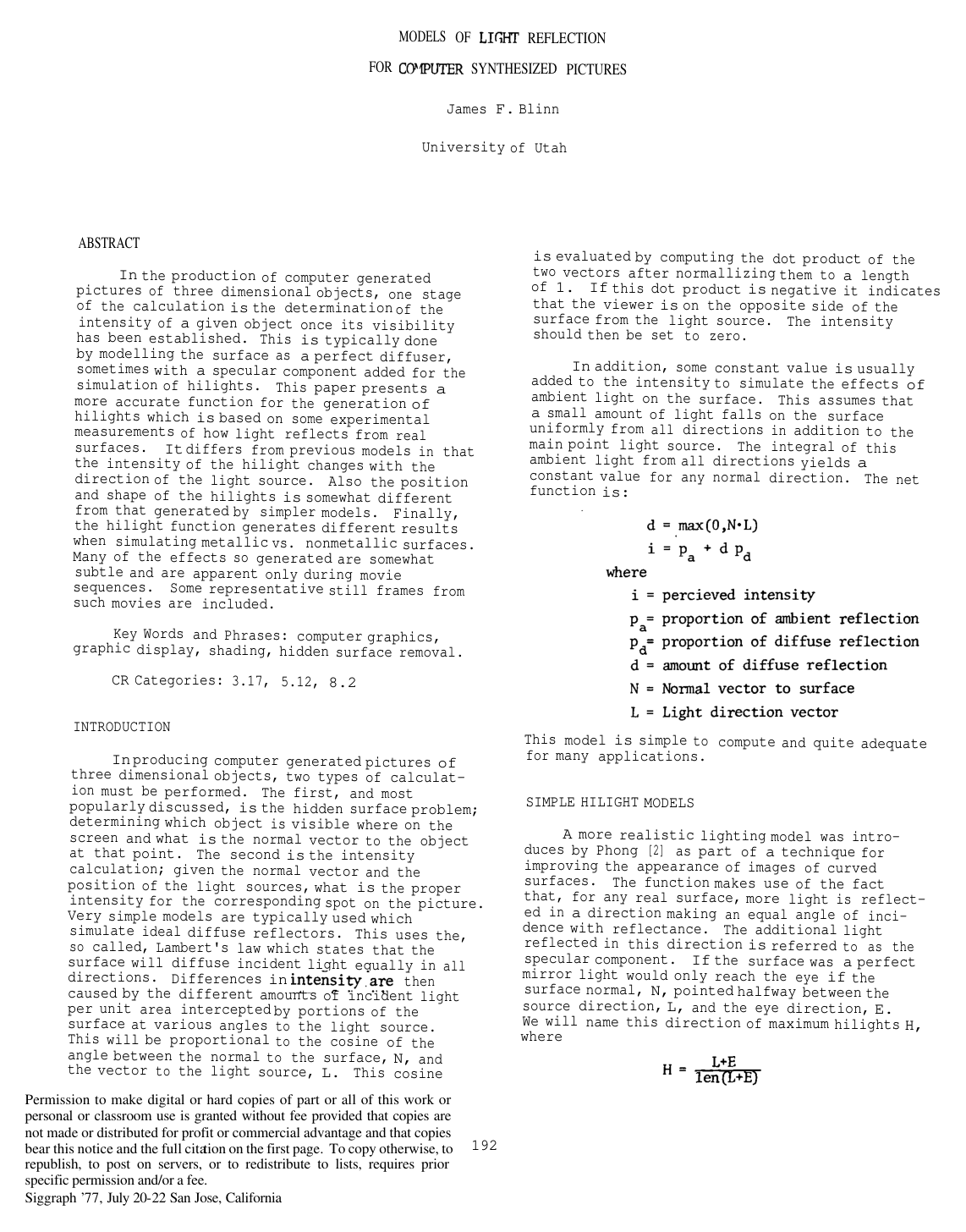
Cover for Models of light reflection for computer synthesized pictures

Abstract

In the production of computer generated pictures of three dimensional objects, one stage of the calculation is the determination of the intensity of a given object once its visibility has been established. This is typically done by modelling the surface as a perfect diffuser, sometimes with a specular component added for the simulation of highlights. This paper presents a more accurate function for the generation of highlights which is based on some experimental measurements of how light reflects from real surfaces. It differs from previous models in that the intensity of the highlight changes with the direction of the light source. Also the position and shape of the highlights is somewhat different from that generated by simpler models. Finally, the highlight function generates different results when simulating metallic vs. nonmetallic surfaces. Many of the effects so generated are somewhat subtle and are apparent only during movie sequences. Some representative still frames from such movies are included.

Table of Contents

  • INTRODUCTION
  • MODELS OF LIGHT REFLECTION FOR COMPUTER SYNTHESIZED PICTURES
  • SIMPLE HILIGHT MODELS
  • TORRANCE-SPARROW MODEL
  • FACET DISTRIBUTION FUNCTIONS
  • COMPUTATIONAL CONSIDERATIONS
  • COMPARISON WITH PHONG SHADING
  • VARYING SURFACE SHININESS
  • CONCLUSIONS
  • REFERENCES

Knowls

  1. Knowl 1 — Torrance-Sparrow Microfacet Specular Reflection Model for Computer Graphics

    model/method

    The net perceived intensity ii at a surface point illuminated by a point light source and ambient light is modelled as:

    i=pa+d pd+s psi = p_a + d \, p_d + s \, p_s

    where:

    • pap_a is the proportion of ambient reflection.
    • pdp_d is the proportion of diffuse reflection.
    • psp_s is the proportion of specular reflection.
    • d=max⁡(0,N⋅L)d = \max(0, N \cdot L) is the diffuse Lambertian reflection component, where NN is the unit surface normal and LL is the unit vector pointing toward the light source.
    • ss is the specular reflection intensity.

    Under the microfacet formulation adapted from Torrance and Sparrow, a surface is modeled as a collection of randomly oriented, mirror-like microfacets. The specular component ss is given by:

    s=D G FN⋅Es = \frac{D \, G \, F}{N \cdot E}

    where:

    • EE is the unit vector pointing toward the observer.
    • DD is the microfacet orientation distribution function, evaluating the fraction of microfacets oriented in the halfway direction HH.
    • G∈[0,1]G \in [0, 1] is the geometrical attenuation factor, accounting for mutual shadowing and masking among adjacent microfacets.
    • FF is the Fresnel reflection coefficient giving the fraction of incident light specularly reflected as a function of incidence angle and refractive index nn.
    • The divisor N⋅EN \cdot E accounts for the increased projected surface area visible to the observer as the surface tilts relative to the viewing direction.
  2. Knowl 2 — Halfway Vector Formulation for Specular Highlights

    definition

    For a point light source in direction LL and an observer in direction EE, specular reflection from mirror-like microfacets reaches the observer only from facets whose local normal aligns with the halfway vector HH. The unit halfway vector is defined as:

    H=L+E∥L+E∥H = \frac{L + E}{\|L + E\|}

    where LL and EE are unit vectors directed from the surface point toward the light source and viewer, respectively.

    The angular deviation α\alpha of a microfacet from the macroscopic surface normal NN satisfies:

    cos⁡α=N⋅H\cos\alpha = N \cdot H

    The local angle of incidence ϕ\phi on microfacets oriented along HH satisfies:

    cos⁡ϕ=L⋅H=E⋅H\cos\phi = L \cdot H = E \cdot H

  3. Knowl 3 — Geometric Attenuation Factor for Symmetric V-Groove Microfacets

    theoretical result

    Under the model of microfacets configured as symmetric V-shaped grooves with opposite walls inclined at equal angles to the average surface normal NN, the geometrical attenuation factor GG represents the proportion of reflected light remaining after masking and shadowing. It is computed as:

    G=min⁡(Ga,Gb,Gc)=min⁡(1, 2(N⋅H)(N⋅E)E⋅H, 2(N⋅H)(N⋅L)E⋅H)G = \min(G_a, G_b, G_c) = \min\left(1, \, \frac{2(N \cdot H)(N \cdot E)}{E \cdot H}, \, \frac{2(N \cdot H)(N \cdot L)}{E \cdot H}\right)

    where:

    • NN is the unit macroscopic surface normal.
    • LL is the unit vector toward the light source.
    • EE is the unit vector toward the viewer.
    • H=L+E∥L+E∥H = \frac{L + E}{\|L + E\|} is the unit halfway vector, satisfying L⋅H=E⋅HL \cdot H = E \cdot H.
    • Ga=1.0G_a = 1.0 corresponds to no geometric obstruction.
    • Gb=2(N⋅H)(N⋅E)E⋅HG_b = \frac{2(N \cdot H)(N \cdot E)}{E \cdot H} accounts for masking, where a portion of light reflected from a facet is intercepted by the adjacent groove wall.
    • Gc=2(N⋅H)(N⋅L)E⋅HG_c = \frac{2(N \cdot H)(N \cdot L)}{E \cdot H} accounts for shadowing, where a portion of incident light is blocked by the adjacent groove wall before reaching the facet.
  4. Knowl 4 — Trowbridge-Reitz Microfacet Distribution Function and Parameter Calibration

    model/method

    The microfacet orientation distribution function DD determines the proportionate area of facets oriented at an angle α=cos⁡−1(N⋅H)\alpha = \cos^{-1}(N \cdot H) to the macroscopic surface normal NN. Modeling microfacets as ellipsoids of revolution yields the Trowbridge-Reitz distribution function:

    D3=[c32cos⁡2α (c32−1)+1]2D_3 = \left[ \frac{c_3^2}{\cos^2\alpha \, (c_3^2 - 1) + 1} \right]^2

    where c3∈[0,1]c_3 \in [0, 1] is the eccentricity parameter of the ellipsoids, with c3→0c_3 \to 0 producing shiny surfaces and c3→1c_3 \to 1 producing diffuse surfaces.

    To establish parameter equivalence across different distribution functions, each function's shininess parameter is calibrated against a common half-intensity angle β\beta (the angle α\alpha where D(β)=0.5D(\beta) = 0.5):

    • For the Phong-type distribution D1=cos⁡c1αD_1 = \cos^{c_1}\alpha: c1=−ln⁡2ln⁡cos⁡βc_1 = -\frac{\ln 2}{\ln \cos\beta}
    • For the Gaussian distribution D2=e−(c2α)2D_2 = e^{-(c_2 \alpha)^2}: c2=ln⁡2βc_2 = \frac{\sqrt{\ln 2}}{\beta}
    • For the Trowbridge-Reitz distribution D3D_3: c3=(cos⁡2β−1cos⁡2β−2)1/2c_3 = \left( \frac{\cos^2\beta - 1}{\cos^2\beta - \sqrt{2}} \right)^{1/2}

    When calibrated with equal half-angles β\beta, D3D_3 exhibits a profile closely matching the Gaussian distribution while being computationally more efficient to evaluate.

  5. Knowl 5 — Fresnel Reflectance Formula for Microfacets

    equation

    The Fresnel reflection factor FF specifies the fraction of unpolarized light incident on a microfacet that is reflected rather than absorbed. For an incidence angle ϕ=cos⁡−1(E⋅H)\phi = \cos^{-1}(E \cdot H) and a material with refractive index nn, the unpolarized reflectance is:

    F(ϕ,n)=12[sin⁡2(ϕ−θ)sin⁡2(ϕ+θ)+tan⁡2(ϕ−θ)tan⁡2(ϕ+θ)]F(\phi, n) = \frac{1}{2} \left[ \frac{\sin^2(\phi - \theta)}{\sin^2(\phi + \theta)} + \frac{\tan^2(\phi - \theta)}{\tan^2(\phi + \theta)} \right]

    where sin⁡θ=sin⁡ϕn\sin\theta = \frac{\sin\phi}{n}.

    Using trigonometric identities, FF can be computed directly without trigonometric evaluations as:

    F=(g−c)2(g+c)2{1+[c(g+c)−1c(g−c)+1]2}F = \frac{(g - c)^2}{(g + c)^2} \left\{ 1 + \left[ \frac{c(g + c) - 1}{c(g - c) + 1} \right]^2 \right\}

    where:

    • c=E⋅Hc = E \cdot H
    • g=n2+c2−1g = \sqrt{n^2 + c^2 - 1}

    For metallic substances (n≫1n \gg 1, e.g., n≈200n \approx 200), F(ϕ,n)F(\phi, n) remains approximately constant at 11 across all incidence angles. For non-metallic substances (nn near 11, e.g., n≈1.8n \approx 1.8), F(ϕ,n)F(\phi, n) is small near normal incidence (ϕ=0\phi = 0) and increases exponentially toward 11 at grazing incidence (ϕ→π/2\phi \to \pi/2).

  6. Knowl 6 — Efficient Evaluation and Singularity Avoidance for Microfacet Shading

    algorithm

    Direct division by N⋅EN \cdot E in microfacet specular evaluation causes numerical instability as N⋅E→0N \cdot E \to 0. The combined factor G′=GN⋅EG' = \frac{G}{N \cdot E} avoids division by zero and eliminates redundant divisions using the following branching procedure:

    Input: Unit vectors NN, LL, EE, HH
    Output: Combined attenuation factor G′=GN⋅EG' = \frac{G}{N \cdot E}
    if (N⋅E)<(N⋅L)(N \cdot E) < (N \cdot L) then
        if 2(N⋅E)(N⋅H)<(E⋅H)2(N \cdot E)(N \cdot H) < (E \cdot H) then
            G′←2(N⋅H)E⋅HG' \leftarrow \frac{2(N \cdot H)}{E \cdot H}
        else
            G′←1N⋅EG' \leftarrow \frac{1}{N \cdot E}
    else
        if 2(N⋅L)(N⋅H)<(E⋅H)2(N \cdot L)(N \cdot H) < (E \cdot H) then
            G′←2(N⋅H)(N⋅L)(E⋅H)(N⋅E)G' \leftarrow \frac{2(N \cdot H)(N \cdot L)}{(E \cdot H)(N \cdot E)}
        else
            G′←1N⋅EG' \leftarrow \frac{1}{N \cdot E}
    return G′G'

    Furthermore, when surface roughness c3c_3 is constant across a frame, the Trowbridge-Reitz distribution D3D_3 is evaluated using precalculated terms:

    k1=1c32−1,k2=k1+1k_1 = \frac{1}{c_3^2 - 1}, \quad k_2 = k_1 + 1 D3=(k2cos⁡2α+k1)2D_3 = \left( \frac{k_2}{\cos^2\alpha + k_1} \right)^2

  7. Knowl 7 — Surface Roughness Texture Mapping

    model/method

    To simulate non-uniform surface roughness across a parametric surface, the Trowbridge-Reitz roughness parameter c3c_3 is spatially modulated via a bivariate texture pattern t(u,v)∈[0,1]t(u, v) \in [0, 1]:

    c3(u,v)=cmin⁡+(1−cmin⁡) t(u,v)c_3(u, v) = c_{\min} + (1 - c_{\min}) \, t(u, v)

    where cmin⁡∈(0,1]c_{\min} \in (0, 1] is the global minimum roughness on the surface.

    To ensure consistent normalization across varying roughness values rather than local normalization to D3(0)=1D_3(0) = 1, the modulated microfacet distribution function is scaled using cmin⁡c_{\min}:

    D3=[cmin⁡ c3cos⁡2α (c32−1)+1]2D_3 = \left[ \frac{c_{\min} \, c_3}{\cos^2\alpha \, (c_3^2 - 1) + 1} \right]^2

    where α=cos⁡−1(N⋅H)\alpha = \cos^{-1}(N \cdot H), preserving correct relative highlight intensity and sharpness across texture variations.

  8. Knowl 8 — Off-Specular and Grazing Angle Specular Enhancement

    empirical result

    Comparing the Torrance-Sparrow microfacet formulation against the empirical Phong shading model reveals characteristic differences depending on the angle of incidence:

    1. Near-normal incidence (30∘30^\circ from surface normal): The reflection distributions produced by the Torrance-Sparrow model and the Phong model are nearly identical.
    2. Grazing incidence (70∘70^\circ from surface normal): The Torrance-Sparrow model generates a significantly larger specular reflection peak than the Phong model, driven by the geometric attenuation factor GG and the Fresnel factor FF. The specular peak also shifts away from the ideal mirror reflection direction toward grazing angles.
    3. Material dependence: Non-metallic materials (e.g., magnesium oxide ceramic with n=1.8n = 1.8, ps=0.667p_s = 0.667, pd=0.333p_d = 0.333, c3=0.35c_3 = 0.35) appear predominantly diffuse under perpendicular illumination, but become more intensely specular than metals (e.g., aluminum with n=200n = 200, ps=0.4p_s = 0.4, pd=0.6p_d = 0.6, c3=0.5c_3 = 0.5) under edge-lit / tangential illumination.

Coverage note — None was omitted; all key contributions including the halfway vector, Torrance-Sparrow graphics formulation, V-groove shadowing/masking, Trowbridge-Reitz distribution, Fresnel reflectance simplification, computational optimizations, and roughness texture mapping are covered.

References

  1. 1.Blinn, J. F. and Newell, M. E. Texture and reflection incomputer generated images. Comm ACM 19, 10(Oct 1976), 542-547
  2. 2.Bui-Tuong Phong. Illumination for computer generated images. Comm ACM 18, 6(June 1975) 311-317
  3. 3.Catmull, E. A. Computer display of curved surfaces. Proc. Conf. on Comptr. Graphics. May 1975 (IEEE Cat. No. 75CH0981-1C) 11-17
  4. 4.Gilpin, F. H. Effect of the variation of the incident angle on the coefficient of diffused reflection. Trans. Illum. Eng. Soc. Vol 5, 1910 854-873
  5. 5.Middleton, W. E. K. and Mungall, A. G. The luminous directional reflectance of snow. J. Opt. Soc. Am. 42, 8(Aug 1952) 572-579
  6. 6.Torrance, K. E. and Sparrow, E. M. Polarization, directional distribution, and off-specular peak phenomena in light reflected from roughened surfaces. J. Opt. Soc. Am. 56, 7(Jul 1966) 916-925
  7. 7.Torrance, K. E. and Sparrow, E. M. Theory for off-specular reflection from roughened surfaces. J. Opt. Soc. Am.. 57, 9(Sep 1967) 1105-1114
  8. 8.Trowbridge, T. S. and Reitz, K. P. Average irregularity representation of a roughened surface for ray reflection. J. Opt. Soc. Am. 65, 5(May 1975) 531-536

Citation

MLA
Blinn, J. F. “Models of Light Reflection for Computer Synthesized Pictures”. Proceedings of the 4th Annual Conference on Computer Graphics and Interactive Techniques, 1977, pp. 192–98, https://doi.org/10.1145/563858.563893.
APA
Blinn, J. F. (1977). Models of light reflection for computer synthesized pictures. Proceedings of the 4th Annual Conference on Computer Graphics and Interactive Techniques, 192–198. https://doi.org/10.1145/563858.563893
Chicago
Blinn, J. F. 1977. “Models of Light Reflection for Computer Synthesized Pictures”. Proceedings of the 4th Annual Conference on Computer Graphics and Interactive Techniques, 192–98. https://doi.org/10.1145/563858.563893.
Harvard
Blinn, J.F. (1977) “Models of light reflection for computer synthesized pictures”, Proceedings of the 4th annual conference on Computer graphics and interactive techniques. ACM, pp. 192–198. Available at: https://doi.org/10.1145/563858.563893.
Vancouver
1. Blinn JF (1977) Models of light reflection for computer synthesized pictures. In: Proceedings of the 4th annual conference on Computer graphics and interactive techniques. ACM, pp 192–198

BibTeX

@inproceedings{Blinn_1977, series={SIGGRAPH ’77}, title={Models of light reflection for computer synthesized pictures}, url={http://dx.doi.org/10.1145/563858.563893}, DOI={10.1145/563858.563893}, booktitle={Proceedings of the 4th annual conference on Computer graphics and interactive techniques}, publisher={ACM}, author={Blinn, James F.}, year={1977}, month=July, pages={192–198}, collection={SIGGRAPH ’77} }
Metadata:Crossref

Access the Paper

This paper is available from its original source. Click below to access the PDF.

Open PDF