The digital Michelangelo project: 3D scanning of large statues

Marc LevoyKari PulliBrian CurlessSzymon RusinkiewiczDavid KollerLucas PereiraMatt GinztonSean E. AndersonJames DavisJeremy Ginsberg

article2000SIGGRAPH1,863 citations

Presents an end-to-end hardware and software system for high-resolution 3D digitization of large cultural artifacts under field conditions, detailing custom laser triangulation scanners and scalable algorithms capable of processing multi-gigabyte models like Michelangelo's David.

Listen

Preserving cultural heritage and analyzing historic sculpture requires high-precision 3D documentation that captures fine surface geometry while operating under strict field constraints in museums. The article details the development and deployment of a specialized hardware and software system designed to digitize the precise shape and surface color of large, fragile cultural masterpieces outside of a laboratory environment.

To demonstrate this system, researchers executed a field campaign in Italy, scanning ten sculptures by Michelangelo, two complete architectural interiors, and over one thousand fragments of an ancient Roman marble map. The hardware combined a customized laser-stripe triangulation scanner mounted on a reconfigurable motorized gantry capable of reaching heights over seven meters, paired with a calibrated digital color camera. The software pipeline integrated algorithms for multi-scan alignment, volumetric surface merging, diffuse reflectance extraction, and point-based multiresolution rendering to manage enormous datasets.

The project successfully captured high-density datasets, including a full scan of the statue of David comprising approximately two billion polygons and seven thousand color images. Laser triangulation achieved depth precision sufficient to clearly resolve chisel marks smaller than one millimeter, allowing potential segmentation of artistic tooling techniques. Storing raw data as run-length encoded range images compressed file sizes by a factor of 18:1 compared to standard uncompressed meshes without information loss. Additionally, multi-view global alignment algorithms and out-of-core volumetric processing enabled the team to merge hundreds of scans and interactively navigate massive models at stable frame rates.

These outcomes demonstrate that high-resolution 3D archives of monumental cultural works are technically achievable under field conditions, though they introduce significant logistical, physical, and calibration challenges. While hardware deflections and mechanical play under field conditions occasionally caused sub-millimeter registration discrepancies, robust software alignment successfully compensated for these errors. The resulting digital assets enable accurate geometric analysis, virtual relighting, and structural preservation without risking physical damage to priceless artifacts.

Future work should focus on implementing automated view-planning software to optimize scan angles and systematically fill inaccessible surface cavities, which could reduce required on-site labor by roughly one quarter. Teams undertaking similar efforts should also incorporate active gantry tracking, robust self-calibration protocols, and lighter, mechanized rigging to reduce operational overhead, labor fatigue, and safety risks in historic environments.

The system encountered certain limitations, notably the inability of optical triangulation to penetrate deep, occluded stone crevices, leaving small gaps in complex geometric areas like carved hair and drapery. Subsurface light scattering within marble introduced depth measurement noise two to three times higher than on ideal surfaces, and the color recovery pipeline did not fully account for non-diffuse inter-reflections. Despite these constraints, confidence remains high in the overall geometric accuracy and archival fidelity of the captured models for scientific, historical, and preservation use.

  • Paper: Zippered polygon meshes from range images, Greg Turk et al. (1994). Read this foundational range-image alignment and mesh-zippering method first to understand the multi-scan registration and surface merging that the Digital Michelangelo pipeline scales up.
  • Paper: A volumetric method for building complex models from range images, Brian Curless et al. (1996). Its volumetric integration of aligned range scans provides the key background for the source’s out-of-core merging of many high-resolution scans.
  • Paper: Multiresolution analysis of arbitrary meshes, Matthias Eck et al. (1995). This arbitrary-mesh multiresolution framework prepares you for the source’s point-based multiresolution rendering of extremely large scanned models.
  • Paper: Decimation of triangle meshes, William J. Schroeder et al. (1992). Its topology-preserving mesh decimation introduces the challenge of reducing dense scan geometry while retaining detail, a concern central to handling the project’s massive models.

No sufficiently relevant recommendations were found.
Cover for The digital Michelangelo project: 3D scanning of large statues

Abstract

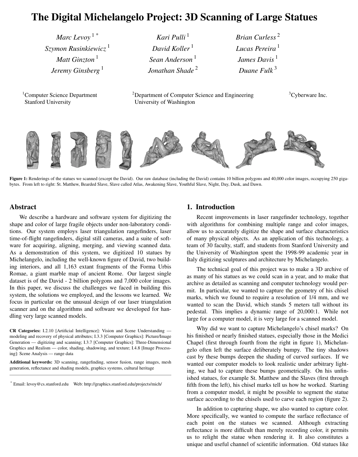
We describe a hardware and software system for digitizing the shape and color of large fragile objects under non-laboratory conditions. Our system employs laser triangulation rangefinders, laser time-of-flight rangefinders, digital still cameras, and a suite of software for acquiring, aligning, merging, and viewing scanned data. As a demonstration of this system, we digitized 10 statues by Michelangelo, including the well-known figure of David, two building interiors, and all 1,163 extant fragments of the Forma Urbis Romae, a giant marble map of ancient Rome. Our largest single dataset is of the David - 2 billion polygons and 7,000 color images. In this paper, we discuss the challenges we faced in building this system, the solutions we employed, and the lessons we learned. We focus in particular on the unusual design of our laser triangulation scanner and on the algorithms and software we developed for handling very large scanned models.

Table of Contents

  • 1. Introduction
  • 2. Scanner design
  • 2.1. Range acquisition
  • 2.2. How optically cooperative is marble?
  • 2.3. Color acquisition
  • 2.4. Gantry: geometric design
  • 2.5. Gantry: structural design
  • 2.6. Calibration
  • 3. Scanning procedure
  • 3.1. Safety for the statues
  • 4. Post-processing
  • 4.1. Range processing pipeline
  • 4.2. Color processing pipeline
  • 5. Handling large datasets
  • 6. Conclusions
  • 7. Acknowledgements
  • 8. References

Knowls

  1. Knowl 1 — Decoupled Multi-Step Global Registration Pipeline for Large Range Scans

    algorithm

    To align hundreds of individual range scans without requiring all scan meshes to reside simultaneously in memory, registration is decoupled into four successive stages: coarse interactive alignment, pairwise Iterative Closest Points (ICP) refinement, exhaustive pairwise ICP between overlapping scans, and constraint-based global iterative relaxation.

    Input: Set of individual scans S={s1,s2,…,sN}S = \{s_1, s_2, \dots, s_N\}
    Output: Globally aligned rigid transformations T1,T2,…,TNT_1, T_2, \dots, T_N
    for each scan si∈Ss_i \in S upon acquisition:
        Interactively position sis_i to roughly match existing scans via manual transformation or 3-point matching
        Select an overlapping scan sjs_j and refine TiT_i using pairwise ICP
    Initialize empty constraint set C←∅C \leftarrow \emptyset
    for each pair of substantially overlapping scans (si,sj)(s_i, s_j) in SS:
        Isolate (si,sj)(s_i, s_j) and run pairwise ICP to compute optimal relative alignment
        Extract matching surface point pairs Pij={(pk(i),pk(j))}P_{ij} = \{(p_k^{(i)}, p_k^{(j)})\} between sis_i and sjs_j
        Store PijP_{ij} in constraint set CC
    Run iterative relaxation on CC to solve for T1,…,TNT_1, \dots, T_N:
        Minimize global registration error across all stored point pairs while holding local point correspondences fixed
    return T1,T2,…,TNT_1, T_2, \dots, T_N

    Separating the local pairwise matching from global relaxation ensures that memory usage scales with the number of matched point pairs rather than the full geometric mesh data.

  2. Knowl 2 — Color-to-Diffuse Reflectance Estimation via Calibrated Inverse Lighting

    equation

    To compute the intrinsic diffuse surface reflectance RR from color imagery (de-shading), incident illumination is treated as a point source with radiant intensity II located at distance rr from the surface. The irradiance EE at a surface point with normal obliquity θ\theta relative to the incident light vector is:

    E=Ir2cos⁡θE = \frac{I}{r^2} \cos\theta

    Under an ideal Lambertian reflection assumption with observed radiance L(ωr)L(\omega_r) reflected toward the camera in direction ωr\omega_r, the surface reflectance is:

    R=L(ωr)E=L(ωr)r2Icos⁡θR = \frac{L(\omega_r)}{E} = \frac{L(\omega_r) r^2}{I \cos\theta}

    To cancel out the unknown radiant intensity II of the luminaire, source distance rr, and the uncalibrated camera gain constant kk, a planar white reference card of known absolute reflectance RcR_c (calibrated against a standard such as Spectralon) is imaged at the scanner standoff distance r=112 cmr = 112\text{ cm} at normal incidence (θc=0\theta_c = 0), yielding reflected radiance Lc(ωr)L_c(\omega_r). The absolute diffuse reflectance of the surface point is then calculated as:

    RRc=L(ωr)Lc(ωr)cos⁡θ  ⟹  R=RcL(ωr)Lc(ωr)cos⁡θ\frac{R}{R_c} = \frac{L(\omega_r)}{L_c(\omega_r) \cos\theta} \implies R = R_c \frac{L(\omega_r)}{L_c(\omega_r) \cos\theta}

    Ambient illumination is eliminated prior to evaluating this formula by capturing image pairs with the spotlight active and inactive, and computing their difference.

  3. Knowl 3 — Volumetric Surface Reconstruction with Space Carving and Spatial Block Partitioning

    model/method

    To combine multiple registered range scans into a single watertight polygon mesh while managing multi-gigabyte models, volumetric signed distance integration is coupled with space carving and spatial partitioning:

    1. Signed Distance Field Accumulation: A dense 3D voxel grid is defined over the object volume. For each voxel near an observed range surface, a weighted running average of signed distances from the voxel to each range surface along the sensor line of sight is updated.

    2. Space Carving: Voxels located strictly in front of observed range surfaces along valid sensor lines of sight are marked as empty. All voxels never intersected by any sensor line of sight are marked as unseen.

    3. Watertight Isosurface Extraction: A continuous zero-crossing isosurface is extracted for observed surface geometry. To bridge unobserved holes, the isosurface is extended along the boundary separating empty voxels from unseen voxels. Triangles generated in this manner are flagged as reconstructed rather than observed to distinguish empirical geometric data from topological completions.

    4. Spatial Block Partitioning: Large volumes are subdivided into independent spatial sub-blocks processed separately in memory. The reconstructed sub-block meshes are stitched into a continuous mesh by identifying and merging duplicate vertices along neighboring block boundaries.

  4. Knowl 4 — Run-Length Encoded Range Image Representation for Large Mesh Storage

    model/method

    Rather than storing 3D scan data as explicit polygon meshes (which require explicit 3D vertex coordinates and triangle index lists), scan geometry is stored as regular 2D range images r(u,v)r(u, v):

    • Implicit Coordinates and Quantization: The grid indices (u,v)(u, v) define lateral coordinates implicitly, while each depth sample rr is stored as a 16-bit integer mapped to 3D Cartesian coordinates via calibration parameters stored in a header.
    • Run-Length Encoding: To skip over invalid range samples caused by occlusions or missing data, the 16-bit depth array is compressed using run-length encoding. For a 2-billion-polygon dataset (such as the statue of David), raw 3D vertex coordinates and index lists require 36 GB of storage, whereas run-length encoded range images reduce storage to 2 GB, achieving an 18:1 lossless compression ratio.
    • Lazy Evaluation: Multi-resolution range image pyramids and 3D triangle meshes are generated lazily on demand during display and volumetric merging by subsampling r(u,v)r(u, v) without persistent storage of intermediate level-of-detail meshes.
  5. Knowl 5 — Confidence-Weighted Multi-Observation Reflectance Blending

    model/method

    To blend redundant diffuse reflectance observations across multiple color images per mesh vertex while eliminating specular highlights and boundary artifacts, reflectances are combined using geometric confidence weighting:

    1. Vertex Confidence Factors: For each valid, unoccluded view of a vertex, an initial confidence weight is computed based on:

      • Surface obliquity relative to the light direction (cos⁡θ\cos\theta).
      • Projected surface area relative to the camera viewing direction.
      • Proximity to the mirror reflection direction (observations near the specular reflection vector are assigned zero weight and discarded, eliminating highlights and avoiding sensor saturation).
      • Distance to silhouette edges with respect to the camera (to avoid lens blur).
      • Distance to silhouette edges with respect to the light source (to avoid penumbral blurring).
      • Proximity to the boundaries of the camera image frame.
    2. Conservative Confidence Smoothing: Confidences are smoothed among neighboring vertices on the mesh to eliminate sharp seams between adjacent photographic frames. The smoothing operation is strictly non-increasing (it only decreases confidence weights, never increases them).

    3. Weighted Accumulation: The final diffuse reflectance Rfinal(v)R_{\text{final}}(v) at mesh vertex vv is computed as:

    Rfinal(v)=∑iwi(v)Ri(v)∑iwi(v)R_{\text{final}}(v) = \frac{\sum_i w_i(v) R_i(v)}{\sum_i w_i(v)}

    where Ri(v)R_i(v) is the individual reflectance derived from the ii-th image and wi(v)w_i(v) is its smoothed confidence weight.

  6. Knowl 6 — Laser Triangulation Scanner and Motorized Gantry Hardware Design

    experimental setup

    The scanning system was engineered for non-contact shape and color capture of large-scale, fragile sculptures under non-laboratory museum conditions:

    • Laser Triangulation Scan Head: Custom-built by Cyberware Inc., containing a 5 mW 660 nm red semiconductor laser diode and a 512×480512 \times 480 pixel CCD sensor. The scan head employs a 20° triangulation angle and a single-sided optical path without beam splitters to minimize head weight (15.5 kg combined with the pan-tilt unit). Operating standoff is 112 cm with a 41 cm baseline, providing a field of view of 14 cm wide×14 cm deep14\text{ cm wide} \times 14\text{ cm deep}, a cross-stripe (YY) sample spacing of 0.29 mm, and a depth (ZZ) resolution of 50 μm50\ \mu\text{m}.
    • Color Acquisition Unit: A Sony DKC-5000 3-CCD digital still camera (1520×11441520 \times 1144 nominal resolution, 0.31 mm physical pixel spacing) with a 25 mm lens locked at 112 cm standoff (25 cm×19 cm25\text{ cm} \times 19\text{ cm} field of view). Illumination is supplied by an aperture-matched (f/8f/8) 250 W quartz halogen lamp focused through fiber optics to provide a 0.3 mm circle of confusion across a ±10 cm\pm 10\text{ cm} depth of field.
    • Motorized Structural Gantry: Comprises an 8-foot base vertical truss, an 83 cm horizontal translation table, a 200 cm vertical translation carriage, and motorized pan/tilt rotation axes (100° range each). Internal sliding lead counterweights dynamically balance horizontal scan-head translation. Using 2-foot, 4-foot, and 8-foot non-motorized extension trusses and a ballast platform supporting up to 600 lbs of counterweights, the scan head reaches 7.59 m above the floor, providing a scannable working envelope of 2 m×4 m×8.5 m2\text{ m} \times 4\text{ m} \times 8.5\text{ m} high.
  7. Knowl 7 — Subsurface Scattering Laser Triangulation Depth Bias and Noise in Marble

    empirical result

    When scanning translucent crystalline stone such as Carrara Statuario marble with a 633 nm laser triangulation rangefinder, subsurface scattering degrades geometric measurement accuracy:

    • Systematic Depth Bias: Internal scattering within the crystalline matrix forms a subsurface illumination volume whose apparent centroid is shifted away from the laser source relative to the true surface reflection point. This centroid displacement introduces a systematic depth error. On Carrara Statuario marble at near-normal incidence and 20° viewing obliquity, the measured depth bias is 40 μm40\ \mu\text{m}.
    • Depth Noise: Local fluctuations in the crystalline grain structure distort the scattered spot profile. While the rangefinder exhibits a 1σ1\sigma depth noise of 50 μm50\ \mu\text{m} on optically cooperative diffuse surfaces, 1σ1\sigma depth noise increases by a factor of 2 to 3 (100–150 μm100\text{--}150\ \mu\text{m}) on unpolished Carrara marble, and degrades further on polished surfaces or under oblique laser incidence angles.
  8. Knowl 8 — Six-Stage Kinematic Geometric Gantry Calibration Model

    model/method

    To transform 2D pixel coordinates in range camera sensor space into 3D Cartesian coordinates in the gantry frame of reference, system kinematics are modeled as the concatenation of six 4×44 \times 4 homogeneous transformation matrices:

    Tglobal=Thoriz Tpan Ttilt Troll Tlaser→head Timg→laser\mathbf{T}_{\text{global}} = \mathbf{T}_{\text{horiz}} \, \mathbf{T}_{\text{pan}} \, \mathbf{T}_{\text{tilt}} \, \mathbf{T}_{\text{roll}} \, \mathbf{T}_{\text{laser}\to\text{head}} \, \mathbf{T}_{\text{img}\to\text{laser}}

    The six calibration stages correspond to:

    1. Timg→laser\mathbf{T}_{\text{img}\to\text{laser}}: 2D mapping from CCD range camera pixel coordinates (u,v)(u, v) to physical coordinates on the planar laser sheet.
    2. Tlaser→head\mathbf{T}_{\text{laser}\to\text{head}}: 2D-to-3D rigid transformation relating the laser sheet coordinate system to reference steel tooling balls mounted on the scan head.
    3. Troll\mathbf{T}_{\text{roll}}: 3D rigid transformation accounting for mounting the scan head in a 90° rolled orientation relative to the pan-tilt carriage.
    4. Ttilt\mathbf{T}_{\text{tilt}}: Position and orientation of the physical tilt rotation axis and nonlinear lookup table converting motor drive commands to physical tilt angles.
    5. Tpan\mathbf{T}_{\text{pan}}: Position and orientation of the pan rotation axis and mapping from drive commands to physical pan angles.
    6. Thoriz\mathbf{T}_{\text{horiz}}: Linear translation mapping along the horizontal gantry arm.

    Vertical translation along the main gantry truss is deliberately excluded from the geometric kinematic model because vertical motion causes structural deflections exceeding the error budget (0.25 mm0.25\text{ mm} position, 0.013∘0.013^\circ orientation), requiring vertical inter-scan alignments to be solved via software registration.

  9. Knowl 9 — Automated Range and Color Scanning Script Workflow

    algorithm

    To minimize acquisition time over large surface areas, scanning motion is executed via an automated script combining low-resolution pre-scanning, precision range sweeping, and spotlight-subtracted color capture.

    Input: Horizontal limits [hmin⁡,hmax⁡][h_{\min}, h_{\max}], pan limits [ϕmin⁡,ϕmax⁡][\phi_{\min}, \phi_{\max}], tilt limits [θmin⁡,θmax⁡][\theta_{\min}, \theta_{\max}]
    Output: Aligned range sweeps and ambient-subtracted color imagery
    for h=hmin⁡h = h_{\min} to hmax⁡h_{\max} step 12 cm12\text{ cm}:
        for ϕ=ϕmin⁡\phi = \phi_{\min} to \phi_{\max}step step 4.3^\circ$:
            Execute fast pre-scan sweep in tilt θ\theta at 5∘/s5^\circ/\text{s} (10 cm/s10\text{ cm/s})
            Identify all tilt angular intervals [θstart,θend][\theta_{\text{start}}, \theta_{\text{end}}] containing valid range data
            for each occupied interval [θstart,θend][\theta_{\text{start}}, \theta_{\text{end}}]:
                Execute precision range scan in tilt θ\theta at 0.5∘/s0.5^\circ/\text{s} (1 cm/s1\text{ cm/s})
                
        if hh corresponds to an alternate horizontal position:
            for ϕ=ϕmin⁡\phi = \phi_{\min} to ϕmax⁡\phi_{\max} step 7∘7^\circ:
                for θ=θmin⁡\theta = \theta_{\min} to θmax⁡\theta_{\max} step 7∘7^\circ:
                    Acquire ambient color image IambientI_{\text{ambient}} with spotlight off
            Turn on and warm up quartz halogen spotlight
            for ϕ=ϕmin⁡\phi = \phi_{\min} to ϕmax⁡\phi_{\max} step 7∘7^\circ:
                for θ=θmin⁡\theta = \theta_{\min} to θmax⁡\theta_{\max} step 7∘7^\circ:
                    Acquire lit color image IlitI_{\text{lit}} with spotlight on
                    Compute difference image Idiff=Ilit−IambientI_{\text{diff}} = I_{\text{lit}} - I_{\text{ambient}}

    Adjacent vertical sweeps overlap by 40% and adjacent horizontal shells overlap by 15% to ensure adequate geometric overlap for pairwise Iterative Closest Points (ICP) registration.

  10. Knowl 10 — Digital Michelangelo Scanning Dataset Metrics for the Statue of David

    data/table

    The physical and operational metrics from digitizing Michelangelo's statue of David illustrate the scale and computational throughput of the scanning pipeline. Physical dimensions of the statue were derived directly from the registered 3D scan data, revealing an actual statue height of 517 cm without pedestal (compared to the historically recorded figure of 434 cm).

    Metric Value
    Statue Properties
    Height without pedestal 517 cm517\text{ cm}
    Surface area 19 m219\text{ m}^2
    Volume 2.2 m32.2\text{ m}^3
    Weight 5,800 kg5,800\text{ kg}
    Raw Dataset Properties
    Number of polygons 2 billion2\text{ billion}
    Number of color images 7,0007,000
    Losslessly compressed raw data size 32 GB32\text{ GB}
    Operational Statistics
    Total size of scanning team 22 people22\text{ people}
    Average staffing in museum 3 people3\text{ people}
    Time spent scanning 360 hours (over 30 days)360\text{ hours (over 30 days)}
    Scanning labor 1,080 man-hours1,080\text{ man-hours}
    Post-processing labor 1,500 man-hours (preliminary)1,500\text{ man-hours (preliminary)}

Coverage note — Brief secondary side-projects described only in caption callouts (such as the dense light field capture of the Night statue, time-of-flight architectural scanning of the Accademia and Medici Chapel, and scanning of the Forma Urbis Romae fragments) were omitted as they represent separate project demonstrations rather than the core contributed technical pipeline.

References

  1. 1.Beraldin, J.-A., Cournoyer, L., Rioux, M., Blais, F., El-Hakim, S.F., Godin, G., ‘‘Object model creation from multiple range images: acquisition, calibration, model building and verification,’’ Proc. 1st Int’l Conf. on 3-D Digital Imaging and Modeling, IEEE, 1997, pp. 326-333.
  2. 2.Beraldin, J.-A., Blais, F., Cournoyer, L., Rioux, M., El-Hakim, S.F., Rodell, R., Bernier, F., Harrison, N., ‘‘Digital 3D imaging system for rapid response on remote sites,’’ Proc. 2nd Int’l Conf. on 3-D Digital Imaging and Modeling, IEEE, 1999, pp. 34-43.
  3. 3.Bergevin, R., Soucy, M., Gagnon, H., Laurendeau, D., ‘‘Towards a general multi-view registration technique,’’ IEEE Trans. PAMI, Vol. 18, No. 5, May, 1996, pp. 540-547.
  4. 4.Bernardini, F., Martin, I., Rushmeier, H., ‘‘High-Quality Texture Synthesis from Multiple Scans,’’ IBM Research Report RC 21656(97598), February, 2000, IBM Research, Yorktown Heights, NY.
  5. 5.Besl, P., McKay, N., ‘‘A Method for Registration of 3-D Shapes,’’ IEEE Trans. PAMI, Vol. 14, No. 2, February, 1992, pp. 239-256.
  6. 6.Chen, Y., Medioni, G., ‘‘Object modeling by registration of multiple range images,’’ Image and Vision Computing, Vol. 10, No. 3, April, 1992, pp. 145-155.
  7. 7.Rocchini, C., Cignoni, P., Montani, C., Scopigno, R., ‘‘Multiple textures stitching and blending on 3D objects,’’ Proc. 10th Eurographics Rendering Workshop, Springer-Verlag, 1999, pp. 119-130.
  8. 8.Curless, B., Levoy, M., ‘‘A Volumetric Method for Building Complex Models from Range Images,’’ Proc. SIGGRAPH ’96, ACM, 1996, pp. 303-312.
  9. 9.Dana, K.J., Nayer, S.K., Ginneken, B.V, Koenderink, J.J., ‘‘Reflectance and Texture of Real-World Surfaces,’’ ACM Trans. on Graphics, Vol. 18, No. 1, January 1999, pp. 1-34.
  10. 10.Debevec, P.E., Malik, J., ‘‘Recovering high dynamic range radiance maps from photographs,’’ Proc. SIGGRAPH ’97, ACM, 1997, pp. 369-378.
  11. 11.Dorsey, J., Edelman, A., Jensen, H.-W., Legakis, J., Pedersen, H.-K., ‘‘Modeling and rendering of weathered stone,’’ Proc. SIGGRAPH ’99, ACM, 1999, pp. 225-234.
  12. 12.Giovannini, P., ‘‘Il ‘San Matteo’ di Michelangelo: analisi delle tracce di lavorazione, studio degli strumenti e osservazioni sulla tecnica di scultura,’’ Rivista dell’Opificio delle Pietre Dure, Vol. 10, 1998, pp. 205-228.
  13. 13.Hebert, M., Ikeuchi, K., Delingette, H., ‘‘A Spherical Representation for Recognition of Free-Form Surfaces,’’ IEEE Trans. PAMI, Vol. 17, No. 7, July, 1995, pp. 681-690.
  14. 14.Heikkila.. J., Silven O., ‘‘A four-step camera calibration procedure with implicit image correction,’’ Proc. CVPR ’97, IEEE, 1997, pp. 1106-1112.
  15. 15.Johnson, A.E., Hebert, M., ‘‘Surface Registration by Matching Oriented Points,’’ Proc. 1st Int’l Conf. on 3D Digital Imaging and Modeling, IEEE, 1997, pp. 121-128.
  16. 16.Jokinen, O., ‘‘Self-calibration of a light striping system by matching multiple 3-D profile maps,’’ Proc. 2nd Int’l Conf. on 3-D Digital Imaging and Modeling, IEEE, 1999, pp. 180-190.
  17. 17.Levoy, M., Hanrahan, P., ‘‘Light Field Rendering,’’ Proc. SIGGRAPH ’96, ACM, 1996, pp. 31-42.
  18. 18.Miller, G., ‘‘Efficient Algorithms for Local and Global Accessibility Shading,’’ Proc. SIGGRAPH ’94, ACM, 1994, Computer Graphics pp. 319-326.
  19. 19.Nayar, S. K., Ikeuchi, K., Kanade, T., ‘‘Shape from Interreflections,’’ Proc. ICCV ’90, IEEE, 1990, pp. 2-11.
  20. 20.Oren, M., Nayar, S.K., ‘‘Generalization of Lambert’s reflectance model,’’ Proc. SIGGRAPH ’94, ACM, 1994, pp. 239-246.
  21. 21.Maver, J., Bajcsy, R., ‘‘Occlusions as a Guide for Planning the Next View,’’ IEEE Trans. PAMI, Vol. 15, No. 5, May, 1993, pp. 417-433.
  22. 22.Pito, R., ‘‘A sensor-based solution to the next best view problem,’’ Proc. ICPR ’96, 1996, pp. 941-945.
  23. 23.Pulli, K., Surface Reconstruction and Display from Range and Color Data, Ph.D. dissertation, University of Washington, 1997.
  24. 24.Pulli, K., ‘‘Multiview registration for large data sets,’’ Proc. 2nd Int’l Conf. on 3-D Digital Imaging and Modeling, IEEE, 1999, pp. 160-168.
  25. 25.Rushmeier, H., Taubin, G., Gue´ziec, A., ‘‘Applying shape from lighting variation to bump map capture,’’ Proc. 8th Eurographics Rendering Workshop, Springer-Verlag, 1997, pp. 35-44.
  26. 26.Rushmeier, H., Bernardini, F., Mittleman, J., Taubin, G., ‘‘Acquiring input for rendering at appropriate levels of detail: digitizing a Pieta`,’’ Proc. 9th Eurographics Rendering Workshop, Springer-Verlag, 1998, pp. 81-92.
  27. 27.Rusinkiewicz, S., Levoy, M., ‘‘Qsplat: a multiresolution point rendering system for large meshes,’’ Proc. SIGGRAPH 2000 (these proceedings).
  28. 28.Sato, Y., Wheeler, M.D., Ikeuchi, K., ‘‘Object shape and reflectance modeling from observation,’’ Proc. SIGGRAPH ’97, ACM, 1997, pp. 379-387.
  29. 29.Tolnay, C., ‘‘Michelangelo,’’ Princeton University Press, 1945.
  30. 30.Wood, D., Azuma, D., Aldinger, K., Curless, B., Duchamp, T., Salesin, D., Stuetzle, W., ‘‘Surface Light Fields for 3D Photography,’’ Proc. SIGGRAPH 2000 (these proceedings).
  31. 31.Yu, Y., Debevec, P., Malik, J., Hawkins, T., ‘‘Inverse global illumination: recovering reflectance models of real scenes from photographs,’’ Proc. SIGGRAPH ’99, ACM, 1999, pp. 215-224.
  32. 32.Zhang, D., Hebert, M., ‘‘Harmonic maps and their applications in surface matching,’’ Proc. Computer Vision and Pattern Recognition (CVPR) ’99, IEEE, 1999, pp. 525-530.

Citation

MLA
Levoy, M., et al. “The Digital Michelangelo Project”. Proceedings of the 27th Annual Conference on Computer Graphics and Interactive Techniques - SIGGRAPH '00, 2000, pp. 131–44, https://doi.org/10.1145/344779.344849.
APA
Levoy, M., Ginsberg, J., Shade, J., Fulk, D., Pulli, K., Curless, B., Rusinkiewicz, S., Koller, D., Pereira, L., Ginzton, M., Anderson, S., & Davis, J. (2000). The digital Michelangelo project. Proceedings of the 27th Annual Conference on Computer Graphics and Interactive Techniques - SIGGRAPH '00, 131–144. https://doi.org/10.1145/344779.344849
Chicago
Levoy, M., J. Ginsberg, J. Shade, et al. 2000. “The Digital Michelangelo Project”. Proceedings of the 27th Annual Conference on Computer Graphics and Interactive Techniques - SIGGRAPH '00, 131–44. https://doi.org/10.1145/344779.344849.
Harvard
Levoy, M. et al. (2000) “The digital Michelangelo project”, Proceedings of the 27th annual conference on Computer graphics and interactive techniques - SIGGRAPH '00. ACM Press, pp. 131–144. Available at: https://doi.org/10.1145/344779.344849.
Vancouver
1. Levoy M, Ginsberg J, Shade J, et al (2000) The digital Michelangelo project. In: Proceedings of the 27th annual conference on Computer graphics and interactive techniques - SIGGRAPH '00. ACM Press, pp 131–144

BibTeX

@inproceedings{Levoy_2000, series={SIGGRAPH ’00}, title={The digital Michelangelo project: 3D scanning of large statues}, url={http://dx.doi.org/10.1145/344779.344849}, DOI={10.1145/344779.344849}, booktitle={Proceedings of the 27th annual conference on Computer graphics and interactive techniques  - SIGGRAPH ’00}, publisher={ACM Press}, author={Levoy, Marc and Ginsberg, Jeremy and Shade, Jonathan and Fulk, Duane and Pulli, Kari and Curless, Brian and Rusinkiewicz, Szymon and Koller, David and Pereira, Lucas and Ginzton, Matt and Anderson, Sean and Davis, James}, year={2000}, pages={131–144}, collection={SIGGRAPH ’00} }
Metadata:Crossref

Access the Paper

This paper is available from its original source. Click below to access the PDF.

Open PDF